Flying a PAR Approach

Here’s a look at a mostly bygone type of instrument approach: a PAR—precision approach radar—procedure. When you fly a PAR, a specially trained controller uses a short-range, highly accurate radar display to talk you down. The controller guides you left and right to remain on the extended runway centerline while also directing you to adjust your descent to follow the proper vertical path. In effect, you fly an ILS, but instead of using localizer and glideslope indicators to help you remain on track, you follow the controller’s instructions.

PAR were standard practice, especially at military airfields in the decades following World War II. You can see dramatized, but realistic depictions of PAR in movies, such as the conclusions of Strategic Air Command, starring Jimmy Stewart, and the first film in the Airport franchise, released in 1970.

The PAR controller in Airport (1970)

The radar displays and other electronics have been updated since, but the basic process remains the same even today. Although a PAR could be useful in an emergency, as in those films, today it’s unlikely that you’ll have a radar approach available nearby if your primary navigation equipment fails. But as I’ll explain a bit later, flying PAR approaches is still an excellent exercise.

In the U.S., only about 100 approaches with “radar minimums” remain in the system. Most of those procedures are at military bases, and the armed forces still use PAR in daily operations.

Some military facilities allow civilian aircraft to fly practice PAR approaches. The controllers need to practice guiding aircraft in, and they’re usually happy to provide the service. You just can’t touch down on the runway at the end of the approach.

In this video, I flew the PAR runway 15 at Gray Army Airfield (KGRF) near Tacoma, WA. It’s mostly home to helicopters, but it also serves fixed-wing aircraft and is part of the Joint Base Lewis-McChord complex.

There is no approach chart for a PAR. Instead, the critical details for radar procedures are shown in the “radar minimums” listings in the Terminal Procedures Publication for each region in which radar approaches are available.

Often when pilots fly a PAR, they load the corresponding ILS for the runway as backup. But for this video, I didn’t want to reference LOC and GS displays. Instead, I hoped to use the PAR to make an important point about instrument flying. As you’ll see, following the controller’s verbal commands forces you to use the control-performance method of instrument flying. You don’t have needles to chase, so you must smoothly and precisely fly specific headings while simultaneously making small pitch and power adjustments to track the correct vertical path. A PAR is a great exercise in precise aircraft control.

Using VNAV on an Approach

Pilots of GA piston singles don’t typically fly STARs, and usually ATC vectors us to join approaches that don’t require many step-downs as we intercept the final approach course. Instead, we tend to use the VNAV (or older VCALC) features in our avionics to meet crossing restrictions, manage the descent from cruise to an initial altitude for an approach, or to help us arrive near an airport at the appropriate traffic pattern altitude.

But when connected to a GPS navigator, such as a Garmin GTN 750 or 650, that supports vertical navigation, new digital autopilots like the Garmin GFC 500 and GFC 600 can automatically descend as you fly the initial legs of an instrument approach, reducing your workload and helping you spend more time monitoring your progress.

To watch VNAV fly a series of published step-downs, join me as I fly the RNAV (GPS) RWY 29 approach at the Skagit Regional airport (KBVS) north of Seattle, an approach that shows the value of using VNAV. I’m in my Beechcraft A36 equipped with the GFC 600 autopilot, a GTN 750Xi, and G500 TXi.

For more information about VNAV, see these additional posts here at BruceAir:

How is an LPV Glidepath Created?

Most of us understand how paired LOC and GS signals provide a course and a glideslope to follow when flying an ILS to a decision altitude (DA). (If you’d like a detailed review, see, for example, How ILS Works on the FlightInsight YouTube channel).

But the glidepath you see when flying an RNAV (GPS) approach to LPV minimums (usually shown as a magenta diamond on the vertical deviation scale) is more mysterious.

As this excellent explanation from Honeywell explains:

To make an LPV mimic an ILS’s behavior, LPV relies on programmed coordinates and instructions contained in a Final Approach Segment (FAS) data block. The FAS data block contains instructions for the approach, including coordinates for the runway, threshold crossing height, elevation, glidepath angle, and horizontal and vertical alert limits. The GPS receiver computes both linear and angular deviation but, as previously mentioned, only angular is displayed. They can be thought of as instructions to provide a pseudo localizer and glideslope. 

In other words, the IFR-approved navigation receiver in your panel receives GPS-WAAS signals from space, and then creates a glidepath. The GP that you see and your AP/FD follows doesn’t emanate from a transmitter on the ground. That’s one reason we have so many RNAV (GPS) approaches with LPV minimums, even at small, quiet airports. Except for runway lights and (optional) approach lights, an approach with LPV minimums that mimics an ILS does not require expensive transmitters on the ground.

You GPS-WAAS receiver uses the same principles to create the advisory glidepaths (e.g., LNAV+V and LP+V) that you can use to help you descend to the MDA when flying a 2D (non-precision) approach, or to fly the vertical guidance on the visual approaches available with the latest GPS navigators.

Using a VDP

Most IFR pilots and students can identify a visual descent point (VDP) on the profile view of an instrument approach chart, as highlighted on the RNAV (GPS) RWY 13 approach at KABR.

And pilots typically can recite an accurate definition of the term, based on the explanations provided in references such as the AIM, the Instrument Procedures Handbook, and the Instrument Flying Handbook.

VISUAL DESCENT POINT− A defined point on the final approach course of a nonprecision straight-in approach procedure from which normal descent from the MDA to the runway touchdown point may be commenced, provided the approach threshold of that runway, or approach lights, or other markings identifiable with the approach end of that runway are clearly visible to the pilot. (P/CG)

In my experience, however, few pilots can explain in detail how they would use a VDP while flying a nonprecision, straight-in approach.

Some FAA guidance provides too-subtle hints. See, for example, the following excerpts from the Instrument Procedures Handbook and the Instrument Flying Handbook.

For short runways, arriving at the MDA at the MAP when the MAP is located at the threshold may require a missed approach for some aircraft. For non-precision approaches, a descent rate should be used that ensures the aircraft reaches the MDA at a distance from the threshold that allows landing in the TDZ. On many IAPs, this distance is annotated by a VDP. (IPH 4-37)

The visual descent point (VDP) is a defined point on the final approach course of a nonprecision straight-in approach procedure. A normal descent from the MDA to the runway touchdown point may be commenced, provided visual reference is established. The VDP is identified on the profile view of the approach chart by the symbol “V.” (IFH 1-21)

By definition, if you fly past the VDP at the MDA, you won’t be able to fly a stable, normal descent that puts your wheels on the pavement in the runway touchdown zone. If you continue at the MDA to the missed approach point, which is often at the runway threshold, you may not be able to land safely even if the runway appears through the mist.

But the definitions don’t describe a plan for using a VDP when you’re flying a nonprecision approach.

I teach IFR pilots to use the VDP as a decision point, much like the DA for a precision approach. In other words, when you arrive at the VDP, if you don’t see the visual references required by 14 CFR § 91.175, you should start the missed approach procedure:

  • Continue along the final approach track until you reach the MAP, and then fly the charted headings and courses.
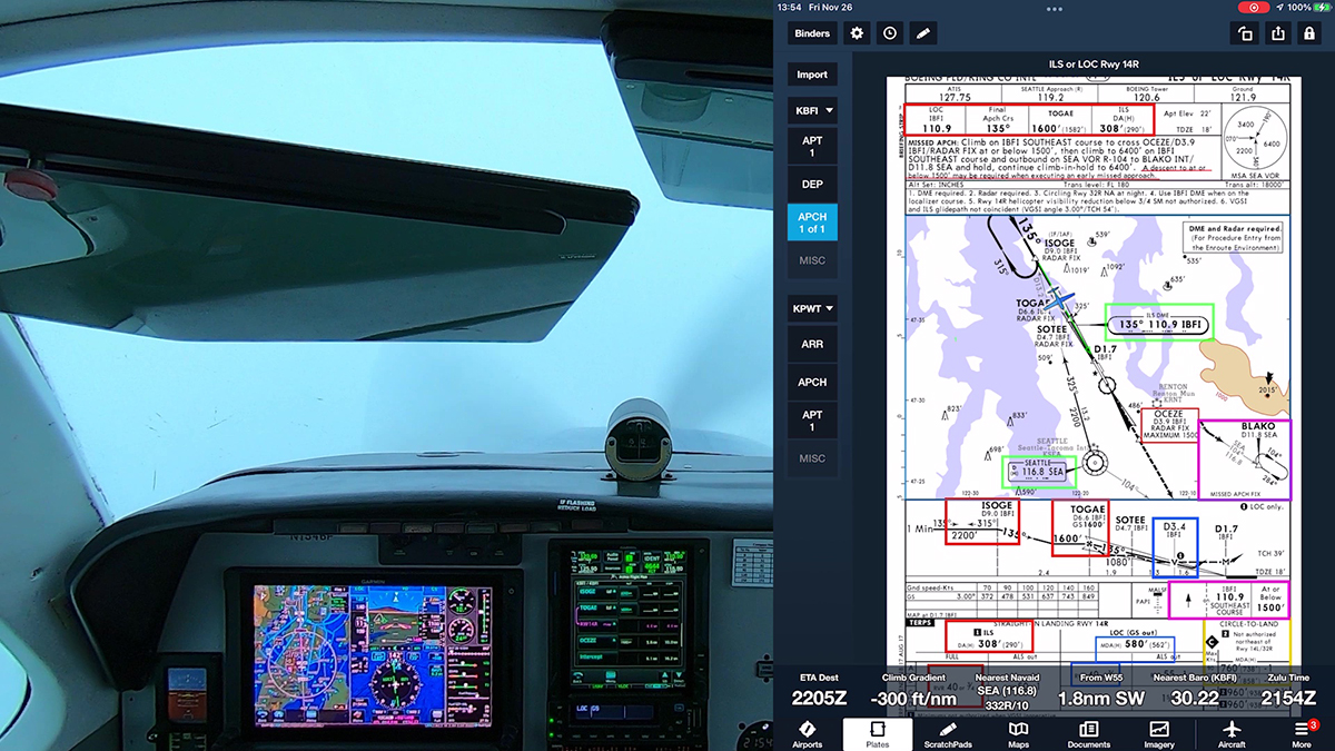
  • Climb to the initial missed approach altitude (unless, as is rarely the case, you must observe an altitude restriction; see, for example, the ILS or LOC RWY 14R at KBFI in Seattle).

Continuing beyond the VDP toward the missed approach point, hoping that you’ll see the runway environment and still be able to land, sets you up for an unstable descent, per the definitions above. You might be able to get a low-performance airplane like a C172 onto a long runway if you leave the MDA between the VDP and the threshold, but in a faster, complex aircraft, pressing on to a landing sets you up for a long landing and perhaps a overrun. Overruns are a continuing problem, especially in jets and other high-performance aircraft, as noted in this AOPA article. They’re also unnecessarily frequent in piston aircraft.

For a demonstration of how to include a VDP in an approach briefing, see Briefing IFR Procedures.

Using a VDP requires preparation. Although VDPs are published on charts, as the AIM notes, VDPs do not appear in the waypoint list when you load an approach in a GPS navigator, such as a Garmin GTN 750.

Note that the Active Flight Plan for the RNAV (GPS) RWY 13 at KABR (see profile view above) includes GUBDE (the FAF), LOWOB (a step-down fix used when flying to the LNAV MDA), and the MAP at the runway 13 threshold. But the VDP, 1.1 nm from the runway, doesn’t appear in the list.

To confirm your position relative to the VDP while flying this approach, you must monitor the distance from the MAP. Or as a paragraph buried deep in AIM 1-1-17 puts it:

If a visual descent point (VDP) is published, it will not be included in the sequence of waypoints. Pilots are expected to use normal piloting techniques for beginning the visual descent, such as ATD [along track distance]. (AIM 1-1-17)

If you have a WAAS-capable GPS navigator, on most approaches you can follow advisory vertical guidance (+V) to the MDA and then on to the runway touchdown zone. An advisory glidepath typically will intercept the MDA near a VDP, but you must monitor the descent carefully. If you use the +V guidance, you also must confirm that you meet any crossing restrictions, especially in the final approach segment, and that you do not descend below the MDA prematurely. Remember that most autopilots will track an advisory glidepath below the MDA unless you intervene.

For more information about advisory vertical guidance while flying conventional approaches, see VOR Approaches with LNAV+V.

Careful review of the profile view for an approach that includes a VDP typically shows that the visual descent point is farther from the runway than the published minimum flight visibility. For the approach at KABR, the VDP is 1.1 nm (1.27 sm) from the threshold. The visibility requirement for category A and B aircraft is 1 sm. In theory, you could continue about another quarter mile toward the runway in hopes of seeing the runway environment. But at a typical C172 IFR approach speed of 90 KIAS, you are traveling 152 ft/sec, and you’ll cover 0.25 nm in about 10 seconds. In this case, using the VDP as the decision point at which you’ll begin the missed approach is not only prudent, it complies with 14 CFR § 91.175(c)(2), which states that you can continue to a landing only if the required visibility is present.

The VDP for other approaches may not so closely approximate the published visibility minimums. See, for example, the RNAV (GPS) Y RWY 16R approach at KPAE.

The VDP is 1.1 nm from the threshold, but the visibility requirement for the straight-in LNAV-only approach is RVR 2400 or one-half sm. You could, in theory, continue about another one-half miles in hopes of picking up the approach lights or other visual references. But do the math. At typical light-piston approach speeds, you’d cover that distance in about 20 seconds, and you’d be that much closer to the runway, still some 400 ft above the touchdown zone. Using the VDP at 1.1 nm from the end of the runway as the decision point ensures that you can make a smooth, stable descent if the runway environment appears. By definition, starting down from the MDA beyond the VDP guarantees that you’ll have to fly a steeper, probably less steady, descent.

Using VNAV During an Instrument Approach

One of the terrific features available in the latest digital autopilots is VNAV, or vertical navigation. If you have a Garmin GTN-series navigator and a GFC 500 or GFC 600 autopilot, you can use VNAV to descend to the charted altitudes along the intermediate legs of an instrument approach, until you reach the final approach fix.

VNAV is also available on most G1000 systems equipped with the GFC 700 autopilot, including the new G1000 NXi, and some other manufacturers, such as Avidyne, plan to add the feature to their systems.

To see another example of using VNAV, visit VNAV with a GFC 600 Autopilot.

The 10-minute video below demonstrates how VNAV can help you fly a smooth, precise descent prior to the FAF. The video explains the basic concepts, uses the Garmin PC Trainer Suite to highlight key details, and then shows VNAV at work as I fly the RNAV (GPS) RWY 12 approach at Kelso, WA (KKLS).

For more information about VNAV, see Garmin GTN VNAV here at BruceAir. Garmin has also posted a detailed explanation of VNAV in the following video.

RNAV Approach at Rural Airport

The Seattle area offers a variety of airports for IFR practice. The flight in the video below takes me from busy Boeing Field (KBFI) to Sanderson Field (KSHN) at Shelton, WA, a non-towered airport just 40 miles southwest of Seattle.

Flying approaches at Sanderson demonstrates how GPS has transformed IFR for light GA aircraft. The airport once had only an NDB approach. Now it has RNAV (GPS) procedures to both runway ends, and the approach to RWY 23, which you’ll see in this video, offers LPV minimums as low as 250 ft AGL and ¾ mi visibility, almost as good as those provided by a category one ILS.

The minimums are a little higher for several reasons—most importantly, RWY 23 does not have an approach lighting system to help guide you in during LIFR conditions. During preflight planning, it’s important to review such details so that you’re not surprised by the view when you break out of the clouds, especially when you are arriving at a relatively quiet, rural airport like Sanderson Field.

Note that this approach has two lines of LPV minimums—one set with a DA of 523 ft and ¾ mi visibility, another with a higher DA of 667 ft and visibility requirement of 1-1/4 miles. Which applies when you fly the approach?

The answer is provided by the hashtag associated with the lower LPV minimums.

The hashtag links to a note at the top of the chart, if you use FAA charts. The note explains that you can use the lower LPV minimums only if, while flying the missed approach, your airplane can achieve a climb gradient of 244 ft/nm until reaching 1700 ft, when the standard terminal climb gradient of 200 ft/nm applies.

Confirming that you can achieve that higher climb gradient requires using the aircraft performance data in the aircraft flight manual or POH, and checking the results against a climb rate/climb gradient table, such as the one published in the Chart Supplement.

As I’ve explained in other videos, I made my own table to more accurately reflect the performance of the aircraft that I fly, and I have rounded up the climb rate numbers to the next highest 100 fpm, a value that I can see on the instruments in the panel.

Ride along as I explain some of the preflight planning process and describe how I use the Garmin G500 TXi, GTN 750Xi, and GFC 600 autopilot in the Beechcraft A36 Bonanza.

A Visual View of an Instrument Approach

I always have instrument students fly their first approaches in visual conditions so that they can see how the displays in the cockpit correspond to the view outside.

Ride along as I fly an RNAV (GPS) approach at Hoquiam, WA (KHQM), and observe how close you come to terrain and other obstacles while following the lateral and vertical guidance, and how, in this case, the autopilot maintains a steady track as it compensates for shifting winds.

This video focuses on the cockpit displays and the view from the camera on the right wingtip. I flew this approach in VMC, and I haven’t included ATC communications or general cockpit views.

You’ll also notice that I mark up charts to help me note important details during preflight planning and to guide me through procedure briefings in the cockpit.

You can learn more about my method for annotating electronic charts in a separate video on my YouTube channel. I also have a video about briefing IFR procedures.

Practicing Instrument Approaches in IMC

I recently took advantage of solid IMC in the Seattle area to fly several instrument approaches. Flying in actual instrument meteorological conditions is different from practicing with a view limiting device (e.g., a “hood”), especially when the visibility beneath the clouds is limited.

Ride along via the videos below as I depart Boeing Field (KBFI) in Seattle to fly the RNAV RWY 20 and ILS RWY 20 approaches at nearby Bremerton National (KPWT) and then return to KBFI via the ILS RWY 14R.

Track of my practice flight.

For more information about my techniques for preparing to fly instrument approaches, see Briefing IFR Procedures here at my blog.

If you’re interested in my recommendations for reviewing and annotating instrument charts, see Annotating IFR Charts, also here at BruceAir.

Staying Flexible During Approaches

I’ve often described techniques for loading approaches to preserve your options should ATC or you need to change plans during the terminal phase of flight.

In the video below, I was cleared for and had started flying the RNAV RWY 24 approach at Hoquiam, WA (KHQM) when a medivac flight on the ground there called Seattle Center to request IFR clearance. KHQM was reporting IFR conditions (OVC 700 with 10 miles visibility), and because the airport has Class E airspace to the surface, that pilot could not depart without a clearance (see Canceling IFR).

The Center controller explained that he couldn’t release the flight until I completed my approach. I offered to take vectors off the procedure to let the other pilot depart, and Center canceled my approach clearance and sent me back to an initial fix.

I was still flying a feeder route, and because I had loaded the approach with an expected initial fix, it was easy to scroll back up the list of fixes and proceed direct to that fix to “reactivate” the procedure when Center reissued the approach clearance.

Enjoy the views of cloud surfing, breaking out of the clouds on final, and flying a coupled missed approach with the GFC 600 autopilot.

Don’t Activate Approaches

Here’s a potentially provocative statement: Don’t activate approaches.

As I have explained in other posts (list below), with most modern GPS navigators, there’s no need explicitly to activate an approach. Activating an approach isn’t magic–that step simply makes the initial fix (called the “transition” in Garmin and other navigators) the current direct-to waypoint.

Don’t activate approaches

In many–perhaps most–cases, proceeding direct to the initial fix you choose when you load an approach is not what you–or ATC–want the navigator to do, at least right now. ATC may assign vectors to the final approach course or clear you to a different initial fix. In particular, if you activate vectors to final (VTF), the fix you need may no longer be visible and available on the moving map and flight plan page, leading to what I call the vectors-to-final scramble. But loading an approach early, with an appropriate initial fix, gives you time to review and brief the procedure–and to prepare for changes that ATC may make to your best-laid plans.

More information:

Avoiding the Vectors-to-Final Scramble

Flying Instrument Approaches without Activating the Approach

Setting a Course v. Vectors to Final

Changes to Vectors-to-Final in Garmin GTN System 6.x

New ATC Phraseology for RNAV Aircraft

A Procedure is Waypoints

When you fly an RNAV approach with a GPS navigator, the system performs a series of calculations and internal tests, such as confirming GPS signal accuracy and precision. As you proceed along feeder routes or vectors toward the final approach fix, the navigator also smoothly narrows the course width from en route to terminal to approach scale, and finally it displays the best available minimums for the approach given your system’s capabilities. But from your perspective in the cockpit, an approach–even when you use a GPS to complement a conventional approach such as an ILS–is essentially a sequence of waypoints, like other legs of a flight plan. Understanding that fact and knowing how to work with flight plans are the keys to setting up an approach and confirming that the procedure is progressing as you expect.

To help you practice using its avionics, Garmin offers free PC-based and iOS trainers (simulations) of its navigators:

On the flight plan page, if the active leg or direct-to fix is below the procedure title, the approach is active.

Instead of explicitly activating an approach, follow these steps to load and fly an approach (the same basic technique also works when flying STARS):

  • Load the procedure you want to fly.
  • For transition, choose a fix appropriate for the direction from which you’re arriving.
  • Load, but don’t activate, the approach. Review the procedure. Wait until you confirm that you’ll receive vectors to join a segment of the procedure or until ATC clears you direct to an initial fix.
  • If ATC vectors you to join a feeder route/transition or the final approach course, activate the appropriate leg of the procedure.
  • If ATC clears you to a fix, proceed direct to that fix.

This technique also keeps the fixes in the flight plan should you want to fly the approach again after flying a missed approach or if you need more time to configure the airplane or deal with a distraction.

Consider the the RNAV (GPS) Y RWY 4 at Moses Lake, WA (KMWH). If you approach KMWH from the east, choose ONPIC or MWH as the transition. If you arrive from the west, choose EDSEW, RUBEL, or ONPIC.

If ATC provides vectors to join the final approach course between ONPIC and UBGUY (the FAF), activate that leg.

But if ATC clears you to MWH, ONPIC, RUBEL, or EDSEW, you can still easily proceed direct and fly the approach beginning at that new point.

Here’s what a sequence beginning at MWH looks like in the Garmin GNS 530W simulator.

Loading the RNAV RWY 04 Y approach with MWH as the transition (initial fix).

The map view shows all the fixes and the course reversal.

The approach title appears in the flight plan, with the fixes after MWH available.

You can proceed direct to MWH to fly the full procedure. Or, to accept vectors to the final approach course, delete the hold and activate the leg between ONPIC and UBGUY.

If you arrive at KMWH from the west, EDSEW is a logical choice for the transition.

Loading EDSEW keeps other fixes in the flight plan and visible on the map.

If you are cleared and proceed direct to EDSEW, the approach is active–because the current direct-to fix is below the procedure title.

If ATC vectors you to join the final approach course outside UBGUY (the FAF), you can activate the leg to UBGUY.

Select UBGUY, press MENU, and choose Activate Leg.

Confirm that you want to activate and fly the leg ONPIC to UBGUY.

The flight plan page shows ONPIC to UBGUY is the active leg.

The active leg (magenta) on the map helps you anticipate the intercept.

Note that with UBGUY, the FAF, as the end of the active leg, the GPS annunciates LPV, another confirmation that the approach is active.

Another Example

Here’s a similar sequence using a Garmin GTN 750 to fly the RNAV (GPS) RWY 34 approach at Arlington, WA (KAWO), north of Seattle. The steps follow the basic logic and presentation used in the GNS 530W.

Here’s flight plan from KBFI to KAWO with SAVOY as an enroute fix above the procedure title. SAVOY appears again below the procedure title as an IAF.

When ATC clears you direct SAVOY, select the instance of SAVOY labeled as an IAF, below the procedure title, and choose direct-to.

Now SAVOY is the active fix, and because it’s below the procedure title, the approach is active.

If you have an electronic PFD such as the Garmin G500 TXi, the waypoint sequence appears below the HSI. Here it shows direct SAVOY (an initial fix), with YAYKU, the FAF, as the next waypoint in the sequence–another confirmation that the approach is active.

As you continue, the GTN 750 sequences to the remaining fixes in the approach toward the missed approach point. The GTN annuciates LPV, confirming the approach is active. If you go missed, the waypoints sequence through to the published missed approach hold.