Most of us understand how paired LOC and GS signals provide a course and a glideslope to follow when flying an ILS to a decision altitude (DA). (If you’d like a detailed review, see, for example, How ILS Works on the FlightInsight YouTube channel).
But the glidepath you see when flying an RNAV (GPS) approach to LPV minimums (usually shown as a magenta diamond on the vertical deviation scale) is more mysterious.
To make an LPV mimic an ILS’s behavior, LPV relies on programmed coordinates and instructions contained in a Final Approach Segment (FAS) data block. The FAS data block contains instructions for the approach, including coordinates for the runway, threshold crossing height, elevation, glidepath angle, and horizontal and vertical alert limits. The GPS receiver computes both linear and angular deviation but, as previously mentioned, only angular is displayed. They can be thought of as instructions to provide a pseudo localizer and glideslope.
In other words, the IFR-approved navigation receiver in your panel receives GPS-WAAS signals from space, and then creates a glidepath. The GP that you see and your AP/FD follows doesn’t emanate from a transmitter on the ground. That’s one reason we have so many RNAV (GPS) approaches with LPV minimums, even at small, quiet airports. Except for runway lights and (optional) approach lights, an approach with LPV minimums that mimics an ILS does not require expensive transmitters on the ground.
You GPS-WAAS receiver uses the same principles to create the advisory glidepaths (e.g., LNAV+V and LP+V) that you can use to help you descend to the MDA when flying a 2D (non-precision) approach, or to fly the vertical guidance on the visual approaches available with the latest GPS navigators.
I recently rode along on an IFR flight that involved an amended clearance during the descent and arrival that pointed out a challenge you may encounter while flying with GPS as your primary navigation source.
The original IFR clearance received before departure ended with a leg from the Beatty VOR (BTY) northwest of Las Vegas, NV direct to the destination, Boulder City Municipal Airport (KBVU).
As we approached BTY, ATC complicated matters with the following amendment:
BTY V135 HIDEN BLD R256 BLD
In plain language, after BTY, we were to join V135, fly to the HIDEN fix, track the 256 radial inbound to the Boulder City VOR (BLD), and finally fly direct to our destination.
The pilot flying was displaying only the magenta CDI that showed us tracking the original route, so the challenge after adding the leg to HIDEN, which could easily be flown while still using GPS, was how to intercept and fly the leg inbound on the 256 radial to BLD. That radial doesn’t correspond to an airway or other defined track on the enroute chart or the chart for the RNAV (GPS) RWY 27 approach at KBVU.
The temptation is to try to build a flight plan leg that defines the inbound course (076) to the VOR. If you have time to set it up, you have a couple of options, such as setting a course to a fix or perhaps creating a user waypoint and adding a leg to the flight plan.
But we were in a speedy descent, already close to BTY. To ensure that we didn’t blow through the radial when we reached HIDEN, I suggested a simple method to help us stay on track until we could reprogram the navigator: Use a bearing pointer tuned and set to the BLD VOR.
That technique allowed us to add HIDEN to the flight plan and continue using GPS to fly along V135.
Using a bearing pointer also meant we wouldn’t have to switch CDI sources as we intercepted the radial. Changing the CDI from GPS to NAV (or vice versa) typically also causes the AP to revert to roll mode, which can lead to “What’s it doing now?” confusion on the flight deck.
Approaching HIDEN we could instead deliberately change the AP to HDG mode, and, using the bearing pointer, intercept the radial inbound to BLD. Once established on the radial, we could confirm that we’d set up the proper course or add a leg to BLD and then continue using GPS in either NAV or LNAV mode (depending on the autopilot) to fly the amended route.
As we approached HIDEN, we watched the tail of the bearing pointer rise toward 256, and as it crossed about the 260 mark, we began a left turn toward the head of the arrow to track the 076 course inbound to BLD.
Once established on the 256 radial, we could have set a direct-to course of 076 to BLD and changed the AP back to NAV/LNAV mode and used GPS to fly to the VOR as cleared.
But as is often the case, ATC started issuing vectors, and we never flew to BLD.
Newer versions of a Garmin PFD, such as the G500 Txi, offer another option—a VOR course preset.
From the Garmin G500 Txi Pilot Guide
If your avionics offer this feature, when the CDI is set to GPS guidance, but you anticipate joining a VOR radial or localizer, you can preset the navaid course you intend to intercept and track. The course preset appears in a window below the HSI.
As you approach the intercept, change the AP/FD to HDG mode (to avoid a sudden turn or change to AP roll mode), then switch the CDI to VOR/LOC. The course arrow will already be set to the course you want to fly. No need to twist the course knob. Fly the appropriate heading to smoothly intercept the VOR/LOC, and continue on your way.
An ATD or simulation such as the free Garmin PC Trainer Suite is an excellent tool to help you practice how to cope with a clearance that involves intercepting a “random radial” and avoid a scramble to comply during a high-workload phase of flight.
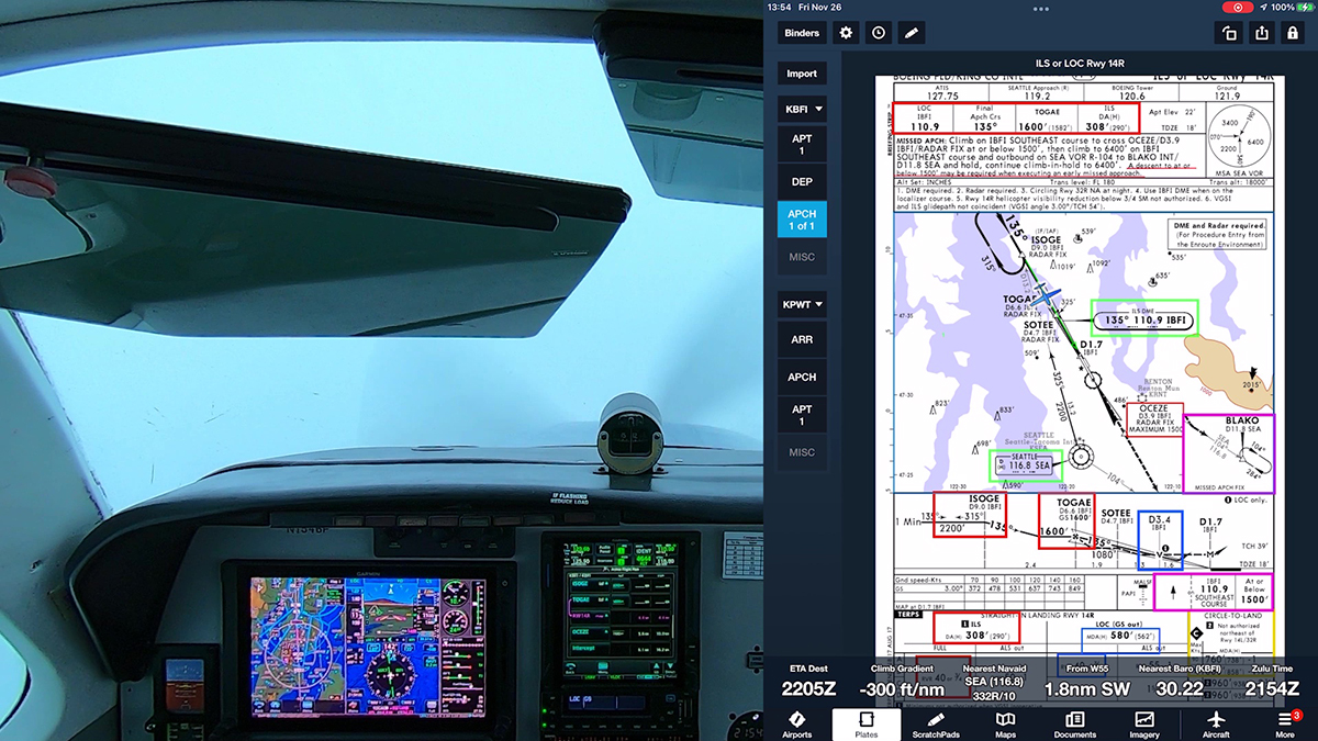
The Seattle area offers a variety of airports for IFR practice. The flight in the video below takes me from busy Boeing Field (KBFI) to Sanderson Field (KSHN) at Shelton, WA, a non-towered airport just 40 miles southwest of Seattle.
Flying approaches at Sanderson demonstrates how GPS has transformed IFR for light GA aircraft. The airport once had only an NDB approach. Now it has RNAV (GPS) procedures to both runway ends, and the approach to RWY 23, which you’ll see in this video, offers LPV minimums as low as 250 ft AGL and ¾ mi visibility, almost as good as those provided by a category one ILS.
The minimums are a little higher for several reasons—most importantly, RWY 23 does not have an approach lighting system to help guide you in during LIFR conditions. During preflight planning, it’s important to review such details so that you’re not surprised by the view when you break out of the clouds, especially when you are arriving at a relatively quiet, rural airport like Sanderson Field.
Note that this approach has two lines of LPV minimums—one set with a DA of 523 ft and ¾ mi visibility, another with a higher DA of 667 ft and visibility requirement of 1-1/4 miles. Which applies when you fly the approach?
The answer is provided by the hashtag associated with the lower LPV minimums.
The hashtag links to a note at the top of the chart, if you use FAA charts. The note explains that you can use the lower LPV minimums only if, while flying the missed approach, your airplane can achieve a climb gradient of 244 ft/nm until reaching 1700 ft, when the standard terminal climb gradient of 200 ft/nm applies.
Confirming that you can achieve that higher climb gradient requires using the aircraft performance data in the aircraft flight manual or POH, and checking the results against a climb rate/climb gradient table, such as the one published in the Chart Supplement.
As I’ve explained in other videos, I made my own table to more accurately reflect the performance of the aircraft that I fly, and I have rounded up the climb rate numbers to the next highest 100 fpm, a value that I can see on the instruments in the panel.
Ride along as I explain some of the preflight planning process and describe how I use the Garmin G500 TXi, GTN 750Xi, and GFC 600 autopilot in the Beechcraft A36 Bonanza.
Pilot Workshops has published updated versions of its Pilot-Friendly manuals for the Garmin GTN 750 and GTN 650 touch-screen navigators. More details and samples here.
Full disclosure: I was the primary author of the new GTN editions, with a lot of help from the editors and graphics staff at Pilot Workshops. I also contribute to the company’s IFR and VFR training scenarios.
The books are available both in spiral-bound print editions and as PDFs.
Most IFR pilots who use GNSS (GPS) are aware that they must load instrument approach procedures (IAPs) by name from the unit’s database. But there’s some confusion in IFR land about flying instrument departure procedures, arrivals, and other routes.
AIM 1−1−17. Global Positioning System (GPS), 2. IFR Use of GPS, includes the following paragraph about IAPs:
(3) All approach procedures to be flown must be retrievable from the current airborne navigation database supplied by the equipment manufacturer or other FAA−approved source. The system must be able to retrieve the procedure by name from the aircraft navigation database, not just as a manually entered series of waypoints. Manual entry of waypoints using latitude/longitude or place/bearing is not permitted for approach procedures. (p. 1−1−20)
That language specifically address IAPs, but it doesn’t mention DPs, STARs, or airways.
If you use an IFR-approved GNSS (see AIM 1−1−17. Global Positioning System (GPS), 2. IFR Use of GPS for the details), you should check the Aircraft Flight Manual Supplement or the AFM (if you fly an aircraft with an IFR-approved GNSS installed as original equipment) for the limitations associated with the unit(s) in your aircraft.
For example, the AFM supplement (a required document for a unit installed under an STC) for the Garmin GNS 530W includes the following language:
2.5 Flight Planning
Whenever possible, RNP and RNAV routes including Standard Instrument Departures (SIDs), and Standard Terminal Arrival (STAR), routes should be loaded into the flight plan from the database in their entirety, rather than loading route waypoints from the database into the flight plan individually. Selecting and inserting individual named fixes from the database is permitted, provided all fixes along the published route to be flown are inserted. Manual entry of waypoints using latitude/longitude or place/bearing is prohibited. (Garmin document 190-00357-03_F)
Similar language appears in the AFM supplements for the GNS 430, GTN 750, and GTN 650 units. For example:
2.4 Flight Planning
Whenever possible, RNP and RNAV routes including Standard Instrument Departures (SIDs), Standard Terminal Arrival (STAR), and enroute RNAV “Q” and RNAV “T” routes should be loaded into the flight plan from the database in their entirety, rather than loading route waypoints from the database into the flight plan individually. Selecting and inserting individual named fixes from the database is permitted, provided all fixes along the published route to be flown are inserted. Manual entry of waypoints using latitude/longitude or place/bearing is prohibited. (AFMS, Garmin GTN GPS/SBAS System, 190-01007-A2 Rev. 8)
You should take care, however, when entering a departure procedure as a series of fixes rather than by name from the database. A DP is more than a series of points defined by LAT/LON. A DP typically contains several types of legs, and you must ensure that you understand how each leg works and how the GNSS in your aircraft handles different leg types and interfaces with your autopilot.
If you use an IFR-approved GNSS (GPS), you’ve probably noticed that the courses shown on the GNSS usually don’t match the numerical values printed on charts, if only by a few degrees. For example, as you fly an instrument procedure, a WAAS GNSS prompts you at each turn point to turn to a new course, but the number displayed on the screen is probably 2-3 degrees different from the number on the chart.
These differences are explained in AIM 1−1−17. Global Positioning System (GPS) , paragraph k. Impact of Magnetic Variation on PBN Systems (p. 1-1-27):
(1) Differences may exist between PBN systems and the charted magnetic courses on ground−based NAVAID instrument flight procedures (IFP), enroute charts, approach charts, and Standard Instrument Departure/Standard Terminal Arrival (SID/STAR) charts. These differences are due to the magnetic variance used to calculate the magnetic course. Every leg of an instrument procedure is first computed along a desired ground track with reference to true north. A magnetic variation correction is then applied to the true course in order to calculate a magnetic course for publication. The type of procedure will determine what magnetic variation value is added to the true course. A ground−based NAVAID IFP applies the facility magnetic variation of record to the true course to get the charted magnetic course. Magnetic courses on PBN procedures are calculated two different ways. SID/STAR procedures use the airport magnetic variation of record, while IFR enroute charts use magnetic reference bearing. PBN systems make a correction to true north by adding a magnetic variation calculated with an algorithm based on aircraft position, or by adding the magnetic variation coded in their navigational database. This may result in the PBN system and the procedure designer using a different magnetic variation, which causes the magnetic course displayed by the PBN system and the magnetic course charted on the IFP plate to be different. It is important to understand, however, that PBN systems, (with the exception of VOR/DME RNAV equipment) navigate by reference to true north and display magnetic course only for pilot reference. As such, a properly functioning PBN system, containing a current and accurate navigational database, should fly the correct ground track for any loaded instrument procedure, despite differences in displayed magnetic course that may be attributed to magnetic variation application. Should significant differences between the approach chart and the PBN system avionics’ application of the navigation database arise, the published approach chart, supplemented by NOTAMs, holds precedence.
The key text is:
…a properly functioning PBN system, containing a current and accurate navigational database, should fly the correct ground track for any loaded instrument procedure, despite differences in displayed magnetic course that may be attributed to magnetic variation application.
Paragraph 2 in that section of the AIM also notes that:
(2) The course into a waypoint may not always be 180 degrees different from the course leaving the previous waypoint, due to the PBN system avionics’ computation of geodesic paths, distance between waypoints, and differences in magnetic variation application. Variations in distances may also occur since PBN system distance−to−waypoint values are ATDs [along-track distances] computed to the next waypoint and the DME values published on underlying procedures are slant−ranged istances measured to the station. This difference increases with aircraft altitude and proximity to the NAVAID.
A similar question also arises when comparing DME and GNSS-derived distances, such as when flying holding patterns.
AIM 5−3−8. Holding provides further details on this issue in:
Substitution of RNAV computed distance to or from a NAVAID in place of DME distance is permitted when holding. However, the actual holding location and pattern flown will be further from the NAVAID than designed due to the lack of slant range in the position solution (see FIG 5−3−7). This may result in a slight difference between RNAV distance readout in reference to the NAVAID and the DME readout, especially at higher altitudes. When used solely for DME substitution, the difference between RNAV distance to/from a fix and DME slant range distance can be considered negligible and no pilot action is required.
At the October 2017 meeting of the Aeronautical Charting Forum, the FAA provided an update on the program gradually to decommission about 309 VORs by 2025 as part of the switch to GNSS-based performance based navigation (PBN).
To see the full list of VORs that FAA plans to decommission, visit this post at BruceAir.
Discontinued 16 VORs to date:
– [EDS] Edisto, in Orangeburg, SC – February 4, 2016
– [BUA] Buffalo, in Buffalo, SD – July 21, 2016
– [PNN] Princeton, in Princeton ME – July 21, 2016
– [PLB] Plattsburgh, in Plattsburgh, NY – September 15, 2016
– [AOH] Allen County , in Lima, OH – September 15, 2016
– [ABB] Nabb, in Nabb Indiana – January 5, 2017
– [SYO] Sayre, in Sayre Oklahoma – April 27, 2017
– [ENW] Kenosha, in Kenosha Wisconsin – June 22, 2017
– [BTL] Battle Creek, in Battle Creek, Michigan – June 22,2017
– [HRK] Horlick, in Horlick Wisconsin – June 22, 2017
– [HUW] West Plains, Missouri – August 17, 2017
– [RIS] Kansas City, Missouri – September 14, 2017
– [DDD] Port City, in Muscatine, IA – October 12, 2017
– [JKS] Jacks Creek, TN – October 12, 2017
– [MXW] Maxwell, CA – October 12, 2017
– [STE] Stevens Point, WI – October 12, 2017
Over the next six months, the following seven VORs are scheduled to be shut down:
– [AOO] Altoona, PA
– [BRD] Brainerd, MN
– [DKK] Dunkirk, NY
– [HVN] New Haven, CT
– [PNE] North Philadelphia, PA
– [RNL] Rainelle, WV
– [RUT] Rutland, VT
You can follow the links in the list above to see the VORs on a VFR chart. Note that these navaids are not the only VORs in the vicinity. In fact, in most cases, at least one VOR is within just a few miles of the facility slated for shutdown.
Part of the switch to the MON is establishing new VOR service volumes. The FAA representative noted that upgrading and flight checking remaining VORs is one the next steps in the VOR MON program. The upgraded service volume values will be 70 nm at or above 5000 ft and 130 nm above 18,000 ft for high VORs. When the flight checks are complete, new information about VOR service volumes will be published in the Chart Supplement and the AIM.
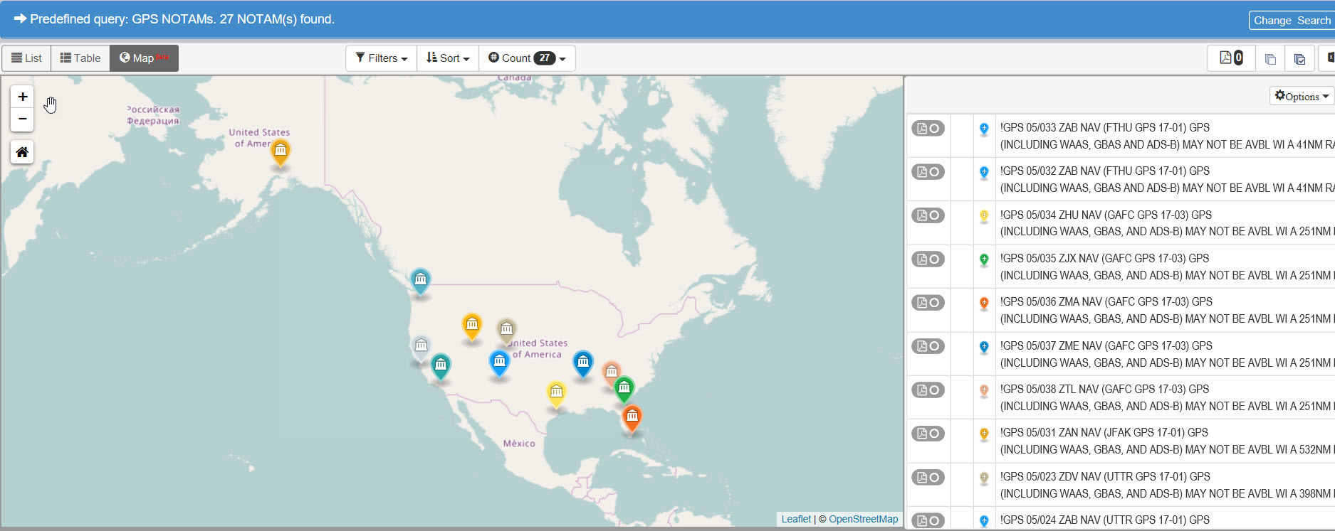
The FAA NOTAM search site (https://notams.aim.faa.gov/notamSearch) provides the quickest way to find GPS NOTAMs that alert you to disruptions in the satellite-based navigation system. If you’ve ever tried to find and sort through the text descriptions of these alerts, you’ll appreciate the lists and map views that show how GPS tests and other issues may affect your ability to navigate using GPS.
To learn more about using the FAA NOTAM search site, you can download the User Guide from the FAA website or from my Aviation Documents folder at OneDrive.
To find GPS-related NOTAMs at the FAA website follow these steps:
After acknowledging the disclaimer, on the main page, select the Predefined Queries option and choose GPS.
Click the Search button, and you’ll see a list of GPS NOTAMs.
You can also show the NOTAMs in a table.
Or in a table with an adjacent map.
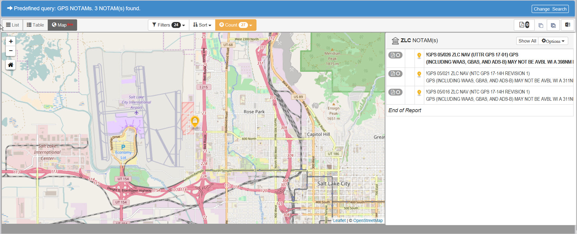
You can filter the list to show only the NOTAMs effective in one or more air route traffic control centers.
And you can zoom in on the map and click a NOTAM flag to see more information about that notice.
Use the +/- buttons in the upper-left corner of the map to zoom in and out. To print a NOTAM, click the print icon next to the text.
FAA has published an update to the AIM, effective 26 May 2016, and it includes a big change if you have an IFR-approved GPS [i.e., a “suitable navigation system” as defined in AC 20-138 and AIM 1-2-3 (b).]
Now, if you fly a conventional approach based on a VOR or NDB (but not a localizer), you can fly the procedure entirely with the GPS, provided you can monitor (using a separate CDI or a bearing pointer) the VOR or NDB facility specified for the approach.
The new language is in section 1−2−3. Use of Suitable Area Navigation (RNAV) Systems on Conventional Procedures and Routes.
The summary of changes to this AIM update notes that:
This change allows for the use of a suitable RNAV system as a means to navigate on the final approach segment of an instrument approach procedure (IAP) based on a VOR, TACAN, or NDB signal. The underlying NAVAID must be operational and monitored for the final segment course alignment.
The new text in the AIM is in paragraph 5 of AIM 1-2-3:
5. Use of a suitable RNAV system as a means to navigate on the final approach segment of an instrument approach procedure based on a VOR, TACAN or NDB signal, is allowable. The underlying NAVAID must be operational and the NAVAID monitored for final segment course alignment.