After flying a low approach at Port Angeles (KCLM) on the north side of the Olympic Peninsula, I picked up my clearance back to Boeing Field (KBFI), which was in a south flow, using runway 14R and 14L.
ATC typically vectors IFR traffic from the north or northwest—from points such as the San Juan Islands and airports on the Olympic Peninsula—to join the localizer for 14R (in fact, ATC really wants you track the final approach course; the LOC is just the time-honored way of accomplishing that goal). Often the clearance comes when you’re 30 to 40 miles from the airport, well outside the 18 nm standard range for a localizer.
When I receive such a clearance, I use a technique, demonstrated in this video, that’s available in most GPS navigators (for more information, see Setting a Course v. Vectors to Final).
A November 2022 update to the AIM includes a note in paragraph 1-1-9 Instrument Landing System, explaining that:
Unreliable signals may be received outside of these areas. ATC may clear aircraft on procedures beyond the service volume when the controller initiates the action or when the pilot requests, and radar monitoring is provided…All charted procedures with localizer coverage beyond the 18 NM SSV have been through the approval process for Expanded Service Volume (ESV) and have been validated by flight inspection.
A figure showing a chart for an ILS at Chicago O’Hare complements the note. It confirms that fixes along a localizer have been verified during the flight check process.
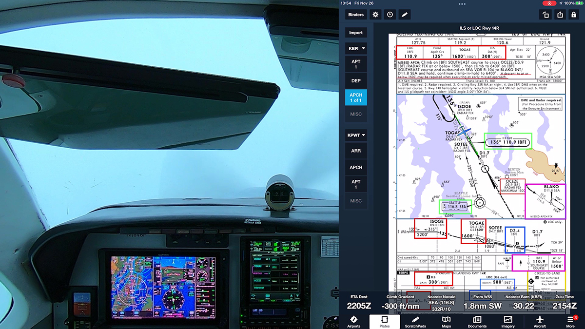
On the chart for the ILS to runway 14R at Boeing Field, however, the fix farthest out on the localizer is ISOGE, recently moved out to 12 nm from the runway, but still within the standard LOC service volume.
As the AIM notes, if ATC is monitoring you, controllers can direct you to join the LOC far from the airport, but such a clearance still leaves you with the problem of intercepting and tracking a course that may be wobbly—if it appears at all.
As the first part of the video shows, after loading the approach and transition, I select the appropriate course to an initial fix along the localizer, and I leave the CDI set to GPS. That setup, similar to using vectors-to-final, but preserving options if ATC changes the plan, draws a magenta reference line along the LOC that I can join and track inbound until I am close enough to receive a stable LOC signal, and then I switch the CDI to green needles.
When you are sure that you’re within the LOC service volume, change the CDI to LOC, and continue the approach with the approved lateral and vertical guidance for an ILS.
Because the weather was VMC when I flew the ILS for this video, I tested the technique and cross-checked what the LOC showed when I was far from the airport. The green needle was, to use a technical term, wonky, until I got close to ISOGE. My track would have been smoother and more accurate had I followed the magenta line until the LOC settled down near the initial fix.
I recently flew the A36 Bonanza to Grant County Airport (KMWH) at Moses Lake in central Washington state. This short video shows a practice ILS in visual conditions to runway 32R, which at 13,500 ft (4,116 m) is one of the longest runways in the U.S. In fact, this runway at the former Larson Air Force Base was an alternate landing site for the Space Shuttle.
If you fly an airplane with a suitable RNAV system (for most of us, that’s an IFR-approved GPS navigator in the panel), you’re accustomed to flying RNAV (GPS) approaches and other procedures, such as RNAV departures and arrivals. And since most RNAV navigators currently in use also support flying ILS and VOR procedures, you also probably still fly the occasional ILS or VOR approach, even if you prefer all-GPS procedures.
But as the shift to Performance-Based Navigation (PBN) continues, the FAA is publishing more approaches that include–and sometimes require–using both GPS-based RNAV systems and ground-based navaids.
Consider the ILS or LOC RWY 12 at Huron (KHON), a small town in South Dakota.
In many respects, this is a typical ILS. It offers a DA at 200 AGL and requires 1/2 sm visibility (the RNAV (GPS) approach to RWY 12 offers the same LPV minimums). It also has an old-school locator outer marker (LOM) at BEADY that serves as the final approach fix for the LOC-only version of the approach and as the anchor for the missed-approach holding pattern.
But read the note in the required equipment box.
In most light aircraft these days, you must also have an IFR-approved GPS to fly the feeder routes and to identify BEADY, because your panel probably doesn’t include DME or an ADF.
ATC could provide vectors to steer you from the enroute environment to the final approach course. But as I’ve noted elsewhere, if you filed IFR as an RNAV/PBN-capable aircraft, a controller can clear you direct to any initial approach or intermediate fix, even if you’re flying a conventional procedure like an ILS.
The enroute chart for the area around Huron shows why you might expect such a clearance. The closest VOR at Watertown (ATY) is nearly 40 nm away, and the airways that converge at KHON are all GPS-based T-routes. The VOR at HON has been decommissioned; only the DME component remains (for more information, see Stand-Alone DMEs on Charts).
A controller can avoid issuing a series of vectors and altitudes as you fly toward the airport and offer one simple instruction, “Cross HUMSO [or WEDEM] at or above 3000, cleared for the ILS RWY 12 approach.”
Your task is to brief the plan for changing from GPS guidance to fly the feeder route from either HUMSO or WEDEM to “green needles” to intercept and track the localizer as you turn inbound toward the airport. And decide, if necessary, how you’ll fly the missed approach.
So today, even if you’re flying to a GA airport far from the big city, you should be prepared to load and fly such hybrid procedures if, for training or practice, you want to fly an ILS, LOC, or VOR approach.
Here’s an airspace puzzle for SUA aficionados: What’s a SMAR (or Special Military Activity Route), as shown on this part of a sectional chart in Nevada, near the Wilson Creek VOR (ILC)?
SMAR look similar to other SUA (e.g., MOAs) on VFR charts. The areas they enclose are outlined with blue hash marks, and they have top and bottom altitudes. Unlike MOAs, restricted areas, and controlled firing areas, however, SMAR don’t have names or numerical designations.
A note on a sectional chart that includes a SMAR explains their purpose.
The chart identifies IFR Military Training Routes and Military Operations Area within which the Department of Defense conducts periodic operations involving Unmanned Aircraft Systems. These aircraft may be accompanied by military or other aircraft which provide the pilots of the Unmanned Aircraft Systems visual observation information about other aircraft operations near them.
In other words, they’re…special, as I learned while attending (virtually) the October 2022 session of the Aeronautical Charting Meeting hosted by the FAA.
A recommendation document submitted by a pilot for discussion (PDF) explained his confusion when he encountered a SMAR on a flight. As he explained to the group, he contacted Flight Service for information, but the specialist couldn’t help, because the pilot couldn’t provide a name for, or other details about, the airspace.
SMARS are noted on the border (but not the legend) of a sectional chart (see below).
But SMAR aren’t described in AIM Section 4. Special Use Airspace, and as the discussion at the meeting revealed, most pilots don’t understand how to get information about the status of a SMAR.
Experts at the ACM did reveal one important detail that’s essential when you want to check the status of a SMAR. These areas are associated with IFR Military Training Routes.
IFR MILITARY TRAINING ROUTES (IR)− Routes used by the Department of Defense and associated Reserve and Air Guard units for the purpose of conducting low-altitude navigation and tactical training in both IFR and VFR weather conditions below 10,000 feet MSL at airspeeds in excess of 250 knots IAS.
P/C Glossary
In the example here, the SMAR outlines the lateral and vertical boundaries of IR200 when it’s being used for SMAR-related activities. So if you want to find out whether a SMAR is in use, check NOTAMS (active IR routes should be included in your preflight briefing) and use the IR number when you contact ATC or FSS.
After a long stretch of widespread fog and icy clouds, the skies in the Puget Sound area cleared—mostly—creating a good opportunity to fly an instrument approach in LIFR conditions at Olympia, the state capital southwest of Seattle.
Ride along in this video at my YouTube channel as I make the short hop in the A36 Bonanza from Boeing Field to fly the RNAV (GPS) RWY 17 approach at KOLM.
The approach offers LPV minimums to the same 200 ft DA and ½ mile visibility as the ILS, and I broke out only a couple of hundred feet above the decision altitude.
The sophisticated avionics and Garmin GFC 600 autopilot in the Bonanza make it easy to fly such approaches. But the skies were busy with training flights, and ATC had its hands full. As you’ll see, one confusing instruction from Seattle Approach had me scratching my head until the controller and I got on the same page.
Most IFR pilots and students can identify a visual descent point (VDP) on the profile view of an instrument approach chart, as highlighted on the RNAV (GPS) RWY 13 approach at KABR.
VISUAL DESCENT POINT− A defined point on the final approach course of a nonprecision straight-in approach procedure from which normal descent from the MDA to the runway touchdown point may be commenced, provided the approach threshold of that runway, or approach lights, or other markings identifiable with the approach end of that runway are clearly visible to the pilot. (P/CG)
In my experience, however, few pilots can explain in detail how they would use a VDP while flying a nonprecision, straight-in approach.
For short runways, arriving at the MDA at the MAP when the MAP is located at the threshold may require a missed approach for some aircraft. For non-precision approaches, a descent rate should be used that ensures the aircraft reaches the MDA at a distance from the threshold that allows landing in the TDZ. On many IAPs, this distance is annotated by a VDP. (IPH 4-37)
The visual descent point (VDP) is a defined point on the final approach course of a nonprecision straight-in approach procedure. A normal descent from the MDA to the runway touchdown point may be commenced, provided visual reference is established. The VDP is identified on the profile view of the approach chart by the symbol “V.” (IFH 1-21)
By definition, if you fly past the VDP at the MDA, you won’t be able to fly a stable, normal descent that puts your wheels on the pavement in the runway touchdown zone. If you continue at the MDA to the missed approach point, which is often at the runway threshold, you may not be able to land safely even if the runway appears through the mist.
But the definitions don’t describe a plan for using a VDP when you’re flying a nonprecision approach.
I teach IFR pilots to use the VDP as a decision point, much like the DA for a precision approach. In other words, when you arrive at the VDP, if you don’t see the visual references required by 14 CFR § 91.175, you should start the missed approach procedure:
Continue along the final approach track until you reach the MAP, and then fly the charted headings and courses.
Climb to the initial missed approach altitude (unless, as is rarely the case, you must observe an altitude restriction; see, for example, the ILS or LOC RWY 14R at KBFI in Seattle).
Continuing beyond the VDP toward the missed approach point, hoping that you’ll see the runway environment and still be able to land, sets you up for an unstable descent, per the definitions above. You might be able to get a low-performance airplane like a C172 onto a long runway if you leave the MDA between the VDP and the threshold, but in a faster, complex aircraft, pressing on to a landing sets you up for a long landing and perhaps a overrun. Overruns are a continuing problem, especially in jets and other high-performance aircraft, as noted in this AOPA article. They’re also unnecessarily frequent in piston aircraft.
For a demonstration of how to include a VDP in an approach briefing, see Briefing IFR Procedures.
Using a VDP requires preparation. Although VDPs are published on charts, as the AIM notes, VDPs do not appear in the waypoint list when you load an approach in a GPS navigator, such as a Garmin GTN 750.
Note that the Active Flight Plan for the RNAV (GPS) RWY 13 at KABR (see profile view above) includes GUBDE (the FAF), LOWOB (a step-down fix used when flying to the LNAV MDA), and the MAP at the runway 13 threshold. But the VDP, 1.1 nm from the runway, doesn’t appear in the list.
To confirm your position relative to the VDP while flying this approach, you must monitor the distance from the MAP. Or as a paragraph buried deep in AIM 1-1-17 puts it:
If a visual descent point (VDP) is published, it will not be included in the sequence of waypoints. Pilots are expected to use normal piloting techniques for beginning the visual descent, such as ATD [along track distance]. (AIM 1-1-17)
If you have a WAAS-capable GPS navigator, on most approaches you can follow advisory vertical guidance (+V) to the MDA and then on to the runway touchdown zone. An advisory glidepath typically will intercept the MDA near a VDP, but you must monitor the descent carefully. If you use the +V guidance, you also must confirm that you meet any crossing restrictions, especially in the final approach segment, and that you do not descend below the MDA prematurely. Remember that most autopilots will track an advisory glidepath below the MDA unless you intervene.
For more information about advisory vertical guidance while flying conventional approaches, see VOR Approaches with LNAV+V.
Careful review of the profile view for an approach that includes a VDP typically shows that the visual descent point is farther from the runway than the published minimum flight visibility. For the approach at KABR, the VDP is 1.1 nm (1.27 sm) from the threshold. The visibility requirement for category A and B aircraft is 1 sm. In theory, you could continue about another quarter mile toward the runway in hopes of seeing the runway environment. But at a typical C172 IFR approach speed of 90 KIAS, you are traveling 152 ft/sec, and you’ll cover 0.25 nm in about 10 seconds. In this case, using the VDP as the decision point at which you’ll begin the missed approach is not only prudent, it complies with 14 CFR § 91.175(c)(2), which states that you can continue to a landing only if the required visibility is present.
The VDP for other approaches may not so closely approximate the published visibility minimums. See, for example, the RNAV (GPS) Y RWY 16R approach at KPAE.
The VDP is 1.1 nm from the threshold, but the visibility requirement for the straight-in LNAV-only approach is RVR 2400 or one-half sm. You could, in theory, continue about another one-half miles in hopes of picking up the approach lights or other visual references. But do the math. At typical light-piston approach speeds, you’d cover that distance in about 20 seconds, and you’d be that much closer to the runway, still some 400 ft above the touchdown zone. Using the VDP at 1.1 nm from the end of the runway as the decision point ensures that you can make a smooth, stable descent if the runway environment appears. By definition, starting down from the MDA beyond the VDP guarantees that you’ll have to fly a steeper, probably less steady, descent.
An example and explanation of the ICAO format is available in this PDF. A similar document is available from NAVCanada here.
Now, don’t panic about having to parse and translate a new NOTAM language. The ICAO format is essentially a data structure, similar to an XML schema. In its raw form, an ICAO NOTAM is really intended to be processed by a computer, not read by a pilot.
The structured format makes it much easier for app developers and service providers, such as ForeFlight, Garmin, Jeppesen, et al. to parse, sort, and display NOTAMS in a pilot-friendly form. Pilots who use EFBs, brief via the web, or view NOTAMS on panel displays won’t typically see NOTAMS presented in the raw ICAO format. Instead, software developers will collect and display the information in the form that they think best for their customers.
For example, the so-called Q-Line contains codes and geographical references for filtering. You don’t need to decode it. That information, along with other details, such as whether the NOTAM primarily affects IFR or VFR operations and a geographic location and radius, will help service providers filter and sort NOTAMS based on the type of briefing requested.
You can see examples of how an automated system processes and displays ICAO NOTAMS at the ICAO website, here.
The new format will also make it easier for NOTAM issuers to create and publish consistent, complete, and detailed notices via a set of new tools.
For more details, see this FAA Webinar on YouTube from August 2021. You can also read background on the issue here (PDF).
I recently completed a long cross-country flight from Boeing Field (KBFI) in Seattle to Nashua, NH (KASH) to participate in a recording session at Pilot Workshops, which produces a range of training and proficiency products for pilots. I am a regular contributor to the IFR Mastery series of IFR scenarios. After the work in Nashua, I returned to Seattle via a southern route.
I have flown many true cross-country, even coast-to-coast, trips, VFR and IFR. I have ferried airplanes, traveled to events such as EAA AirVenture, helped Pilots N Paws get pets to new homes, and made many personal treks throughout the West. But this trip was my first coast-to-coast flight with all the tools and resources currently available to a GA pilot.
For several reasons, I chose to fly the A36 rather than ride the airlines. It had been a couple of years since I’d made such a long-distance trip in the Bonanza, and I wanted to exercise the latest avionics upgrades (viz., G500 TXi, GTN 750Xi, and GFC 600 autopilot) that had been installed just as the pandemic began. Of course, I was an early adopter of ForeFlight on an iPad Mini, connected to the panel with a Flight Stream 510. I also wanted to avoid crowded airliners and airport terminals, and I visited friends along the way.
Videos from the Flight
Videos from the trip are available at my YouTube channel. See the Across the U.S. in a Bonanza playlist to watch the flights in the order flown, including videos of three sightseeing trips not included in the data below.
An RNAV Approach at KSBM
The video below shows the landings at all the stops along the route.
Flight Statistics
Here are the basic statistics for the round-trip flight, not including three side trips. To view each planned route of flight on a chart at SkyVector.com, click the links in the Flight Leg column.
Of course, a nonstop direct route on a trip of this length isn’t possible in a typical single-engine piston. For example, I chose to fly airways across the Cascades and Rockies on the first segment to Billings (KBIL), but even that route isn’t significantly longer than a direct flight (603 nm versus 577 nm).
I also flew west via a T-route around the Chicago Class B airspace on the IFR leg from KSBM to KASW rather than file a direct route across Lake Michigan (294 nm flown v. 288 nm direct).
As you can see in the summary table above, the total distance I flew (as recorded in ForeFlight) was, in the end, only 266 nm longer than direct routes would have been. That’s just a couple of hours’ flying time in the A36, even on such a long round trip of 5625 nm and some 37 hours of Hobbs time. And in the real world, zigs and zags to avoid weather and SUA airspace or to follow ATC vectors always add to theoretical direct distances. For a detailed discussion of this point, see Flying (and Filing) Direct v. Airways.
Transformational Tech
Before I get into specifics about the technology that I used, let me emphasize a key point. New avionics and services such as SiriusXM and FIS-B don’t make the airplane more capable. Even with a modern glass panel, my A36 can’t fly higher, faster, or father than it did when it left the factory in 1989. It still can’t tango with ice or duel with thunderstorms.
And state-of-the-art, integrated avionics–including a modern digital autopilot that’s fully connected to the other boxes in the panel–may not be necessary for typical IFR flights of 2-3 hours to familiar places.
The ability to fly those RNAV (GPS) procedures offered more options on a couple of IFR legs, and it certainly reduced the stress of flying over areas of widespread IFR. Except in the sparsely populated West, I always had several airports with LPV minimums available nearby. Basic GPS was also vital. Several VORs and DMEs were out of service, or procedures were NA unless your aircraft was equipped with a “suitable RNAV system” based on GPS.
More Capable Pilots
But the benefits of the latest avionics and associated technology go beyond flying specific IFR procedures. We all recognize that tools like ForeFlight make planning, filing, and adapting while enroute much easier than in the days of paper charts and phone calls to FSS. A modern glass panel, besides being more reliable than a set of mechanical gauges, helps you collect and process information and reduces time spent estimating ground speed, fuel requirements, and other details, leaving more brain cycles for maintaining situational awareness and making informed decisions before a situation becomes tense.
In other words, today’s avionics and related technologies make you–the pilot–more capable, if you use them wisely.
For example, ForeFlight’s organized preflight briefings guided me through the details of complex weather and helped me review NOTAMS and other information. Not taking dictation from an FSS briefer meant I could see, absorb, and interpret important information, especially when operating in unfamiliar areas. I felt well prepared for each leg.
Features such as recommended routes simplified flight planning and gave me more time to consider options. Choosing a recommended route also meant I was always cleared as filed, reducing potential for confusion and errors before takeoff. Flight Stream connectivity made data entry errors less likely and saved time before takeoff because I could send routes directly from ForeFlight to the GTN 750Xi.
ForeFlight also helped me choose IFR alternates, which I selected not just to meet legal requirements, but also based on comments about FBOs, fuel prices, and availability of services, all of which were presented in the app. Note that I didn’t choose airports with the cheapest fuel. I selected airports that offered or were near services such as maintenance, hotels, rental cars, and airline rides, should they have been needed. (Thankfully, the A36 performed flawlessly.)
The performance calculations in ForeFlight were surprisingly accurate. When I checked my actual progress against the ForeFlight navigation log, I was always within a minute or two of the ETA at a particular fix and fuel used was within a couple of gallons of the preflight estimates.
Speaking of fuel, I had CiES fuel senders installed as part of the last panel update. I had calibrated and proven them before I launched on the trek to the East Coast, but they showed their value on this flight. I always knew exactly how much fuel I had used, and checking the fuel computer in the GTN 750 Xi at every tank switch confirmed that I would have at least my one-hour reserve when I landed, even if my route had changed. I impressed the line techs at each stop with my estimates, always within one gallon, of how much fuel would be needed to top the tanks.
In the past, I carried boxes of paper charts that might expire at some point. In fact, a data update occurred while I was enroute to NH, but updating both ForeFlight and the boxes in the panel took only a few minutes. More importantly, I knew that I always had the proverbial “all available information”–including charts, the Chart Supplement, and other data–while preparing for and flying a leg, regardless of how many boundaries I crossed.
SiriusXM satellite weather, not limited by range like FIS-B, is valuable on long trips. But even FIS-B weather is a godsend, especially when displayed on a tablet and in the panel. On the leg to KSBM, I could see far ahead of ATC, and I requested a reroute that kept me clear of an area of thunderstorms as they moved north, away from my destination.
Enduring Impressions
This trip reinforced impressions from earlier cross-country adventures.
I’m always surprised by how empty the skies can seem. I certainly didn’t see many aircraft, except at airports. And often I was tempted to ask ATC for radio check to make sure that the quiet frequency wasn’t a sign of a radio failure in my airplane.
ATC provided professional, helpful service no matter where I flew. The accents of the controllers changed subtly as I cruised into different regions of the country, but the calm efficiency of the folks on the other side of the conversation didn’t vary, even when weather and traffic complicated the situation.
I waited out a couple of vigorous fronts, both in Maryland and in Albuquerque, but in general, the weather cooperated. I had only three solid IFR legs, and ice, thunder, and other hazards never threatened. I always had comfortable alternatives.
And finally, a modern digital autopilot is transformational. At a basic level it reduces mental and physical fatigue. But having confidence in its ability reliably to fly procedures, and new features such as VNAV, make single-pilot IFR operations immeasurably safer and more comfortable. In fact, although I flew this trip solo, I operated as if I were as part of crew, and that made the adventure across the astonishing variety of landscapes that is America not only possible, but enjoyable.
The October 7, 2021 edition of the Aeronautical Chart Users’ Guide notes that IFR en route charts now show expanded VOR standard service volumes that are being implemented to support the minimum operational network (MON). That network is a key part of the FAA plan to reduce the number of ground-based navigation aids (for more information see Latest on VOR Decommissioning and related posts here at BruceAir).
The new ACUG includes the following note:
IFR ENROUTE CHARTS
Two new VHF Omnidirectional Radio Range (VOR) standard service volumes (SSV) have been implemented in order to achieve VOR service within 70 nautical miles above 5,000 feet above ground level (AGL). The new NAVAID codes are VOR Low (VL) and VOR High (VH). Along with that effort, two new distance measuring equipment (DME) SSVs of DME Low (DL) and DME High (DH) have been implemented to support DME-DME RNAV service. Legacy SSVs of Terminal (T), Low (L), and High (H) will continue to be maintained.
In the past, NAVAIDs at one location typically all had the same SSV. For example, a VORTAC typically had a High (H) SSV for the VOR, the TACAN azimuth, and the TACAN DME, or a Low (L) or Terminal (T) SSV for all three. A VOR/DME typically had a High (H), Low (L), or Terminal (T) for both the VOR and the DME. A common SSV may no longer be the case at all locations. A VOR/DME, for example, could have an SSV of VL for the VOR and DH for the DME, or other combinations.
FAA has released a new edition of the Airplane Flying Handbook (FAA-H-8083-3C). You can download the free PDF from the FAA website here.
The front matter of the new edition lists the following “major revisions”:
Removed mandatory language or cited applicable regulations throughout handbook.
Chapter 1 (Introduction to Flight Training) – Added information on the FAA Wings Program.
Chapter 2 (Ground Operations) – Added a new graphic and information regarding detonation. Now uses the same marshalling graphic as the AMT General Handbook. Updated material on hand propping to match the material in the AMT General Handbook (it doesn’t matter whether a pilot or mechanic is hand propping).
Chapter 3 (Basic Flight Maneuvers) – Corrected G1000 and indications of slip and skid graphics.
Chapter 4 (Energy Management) – All new chapter/material. Incremented the existing chapters 4-17 by 1 (now there are 18 chapters in total).
Chapter 5 (Maintaining Aircraft Control) – Revised the order in which the material was presented.
Chapter 7 (Ground Reference Maneuvers) – Corrected errors in text and graphics for eights on pylons.
Chapter 9 (Approaches and Landings) – Added information concerning a forward slip to a landing and corrected Figure 9-6. Changed description associated with Crosswind Final Approach. Removed material on 360 degree power-off landing as this maneuver is not part of testing standard.
Chapter 10 (Performance Maneuvers) – Added information on lazy eights.
Chapter 11 (Night Operations) – Revised to align with material from CAMI.
Chapter 13 (Transition to Multiengine Airplanes) – Incorporated the addendum. Corrected G1000 displays and force vectors on figures. Accelerated approach to stall minimum altitude revised to match the ACS. The 14 CFR part 23 certification standard used for many multiengine airplanes is now referred to a historical standard, since many of the previous requirements will not apply to newly certificated aircraft.
Chapter 14 (Transition to Tailwheel Airplanes) – Made minor revision regarding handling characteristics.
Chapter 15 (Transition to Turbopropeller-Powered Airplanes) – Addressed an NTSB recommendation regarding slow spool up time of split-shaft engines and corrected figure of fixed-shaft engine gauges.
Chapter 16 (Transition to Jet-Powered Airplanes) – Removed extra information that appears unrelated to flying a turbojet and added information regarding energy management and distance versus altitude in a descent.
Chapter 18 (Emergency Procedures) – Revised information regarding the safety of turning back after an engine failure after takeoff. Added a section on emergency response systems to include ballistic parachutes and autoland systems. Corrected figures of G1000 displays.