How is an LPV Glidepath Created?

Most of us understand how paired LOC and GS signals provide a course and a glideslope to follow when flying an ILS to a decision altitude (DA). (If you’d like a detailed review, see, for example, How ILS Works on the FlightInsight YouTube channel).

But the glidepath you see when flying an RNAV (GPS) approach to LPV minimums (usually shown as a magenta diamond on the vertical deviation scale) is more mysterious.

As this excellent explanation from Honeywell explains:

To make an LPV mimic an ILS’s behavior, LPV relies on programmed coordinates and instructions contained in a Final Approach Segment (FAS) data block. The FAS data block contains instructions for the approach, including coordinates for the runway, threshold crossing height, elevation, glidepath angle, and horizontal and vertical alert limits. The GPS receiver computes both linear and angular deviation but, as previously mentioned, only angular is displayed. They can be thought of as instructions to provide a pseudo localizer and glideslope. 

In other words, the IFR-approved navigation receiver in your panel receives GPS-WAAS signals from space, and then creates a glidepath. The GP that you see and your AP/FD follows doesn’t emanate from a transmitter on the ground. That’s one reason we have so many RNAV (GPS) approaches with LPV minimums, even at small, quiet airports. Except for runway lights and (optional) approach lights, an approach with LPV minimums that mimics an ILS does not require expensive transmitters on the ground.

You GPS-WAAS receiver uses the same principles to create the advisory glidepaths (e.g., LNAV+V and LP+V) that you can use to help you descend to the MDA when flying a 2D (non-precision) approach, or to fly the vertical guidance on the visual approaches available with the latest GPS navigators.

RNAV Approach at KCLS

I flew an RNAV (GPS) approach at Chehalis, WA (KCLS) to show how low LPV minimums can take you, even to a runway at a typical small-town, non-towered airport that doesn’t have approach lights and other components associated with precision approaches. I flew this procedure in VMC to help you see the runway environment.

Now, an RNAV (GPS) approach to LPV minimums isn’t technically a precision approach, at least according to the current ICAO definition of the term. But as a practical matter, flying to a localizer performance with vertical guidance DA is just like flying an ILS. The lateral guidance funnels you toward the runway, just like a localizer, and the glidepath generated by the GNSS box in the panel acts just like an ILS glideslope. In fact, I prefer flying an LPV approach even when an ILS is available. You don’t have to switch navigation sources, there are no false glideslopes, and there is no ILS critical area.

If the runway served by the RNAV (GPS) approach doesn’t also have an ILS, you probably won’t see approach and runway lights except for edge lighting. And the minimums (DA and visibility) will be a little higher than they would be for a typical category 1 ILS (i.e., 200-1/2). At KCLS, the LPV minimums are 300 AGL (DA 476) and 1 mile.

But those minimums are a substantial improvement over the LNAV MDA (900 MSL; 724 AGL), the lowest you can go without the approved vertical guidance available with WAAS.

Handy WAAS and RNAV (GPS) Approach Fact Sheets

You can find a couple of handy FAA fact sheets on WAAS and RNP Approaches (which most of us know as RNAV (GPS) approaches at the FAA website, here.

The WAAS fact sheet outlines the advantages of a WAAS-capable navigator.

Required Navigation Performance (RNP) Approaches (APCH) succinctly explains the different lines of minimums and provides helpful references to ACs, the AIM, etc.

New FAA Policy on IFR Alternates with GPS

The FAA has updated its policies for filing alternate airports for pilots who use an IFR-approved GPS.

According to the new policy, which will be added to future versions of the AIM, advisory circulars, and other documents, pilots with non-WAAS GPS navigators can now file an alternate airport that is served only by GPS-based instrument approaches, provided the original destination airport has ground-based procedures, or vice-versa.

Pilots flying WAAS-equipped aircraft with baro-VNAV capability (typically only business jets and airliners) can now use the LNAV/VNAV decision altitude for applicable alternate airport weather minimums.

Pilots without baro-aided LNAV/VNAV capability must still meet the requirements of 14 CFR § 91.169, which specifies alternate airport weather minima for non-precision approach procedures. In other words, at the estimated time of arrival at the alternate airport, the forecast weather at the alternate must call for a ceiling of at least 800 feet and visibility of at least 2 statute miles.

The new NOTAM, issued April 4, explains that:

The FAA [has] also studied the availability of GPS and Wide Area Augmentation System (WAAS) for GPS­ and WAAS-based instrument approaches at destination and alternate airports. As a result, the FAA has updated the policy and provided clarification to enable additional flexibility for users while maintaining safety in the National Airspace System (NAS).

Non-WAAS Users

For pilots who fly with IFR-approved GPS navigators without WAAS capabilities, the NOTAM explains that:

The current alternate airport planning policy allows users equipped with non-WAAS navigators…to plan for GPS-based instrument approach procedures (IAP) at their destination but not at their alternate airport.

The FAA has updated this policy to allow an option to flight plan for use of a GPS-based IAP at either the destination or the alternate airport, but not at both locations. At the alternate airport, pilots may plan for applicable alternate airport weather minimums using:

1. Lateral navigation (LNAV) or circling minimum descent altitude (MDA);

2. LNAV/vertical navigation (LNAV/VNAV) decision altitude (DA) if equipped with and using approved barometric vertical navigation (baro-VNAV);

3. RNP 0.3 DA on an RNAV (RNP) IAP if specifically authorized with approved baro-VNAV equipment.

…The FAA based this policy clarification on the facts that GPS-based lateral guidance is the same for LNAV, LNAV/VNAV and RNP 0.3 DA and approved barometric vertical navigation equipment does not rely on GPS information. Therefore, a loss of GPS vertical would not affect these WAAS users navigating vertically with baro-VNAV.

WAAS Users

The change in policy for WAAS users does not affect most pilots who fly light GA aircraft with IFR-approved WAAS navigators. According to the NOTAM:

The current alternate airport planning policy explicitly prohibits TSO-C145() and TSO-C146() equipped users (WAAS users) from planning to use WAAS vertical guidance at their alternate airport.

There are some WAAS integrations that use baro-VNAV for vertical guidance. WAAS users should consult their flight manuals for this information. This policy clarification allows properly trained and approved, as required, WAAS users equipped with and using approved baro-VNAV equipment to plan for applicable alternate airport weather minimums using:

1. LNAV/VNAV DA at an alternate airport.

2. RNP 0.3 DA on an RNAV (RNP) IAP at the alternate airport if specifically authorized.

The FAA based this policy clarification on the facts that GPS-based lateral guidance is the same for LNAV, LNAV/VNAV and RNP 0.3 DA and approved barometric vertical navigation equipment does not rely on GPS information. Therefore, a loss of GPS vertical would not affect these WAAS users navigating vertically with baro-VNAV.

LP Approaches are now Available

The 7 February 2013 NavData update from Jeppesen includes RNAV approaches with LP (localizer performance) minimums. You can read more about LP at my blog here and in AIM 1-1-20 (b)(3):

A new nonprecision WAAS approach, called Localizer Performance (LP) is being added in locations where the terrain or obstructions do not allow publication of vertically guided LPV procedures. This new approach takes advantage of the angular lateral guidance and smaller position errors provided by WAAS to provide a lateral only procedure similar to an ILS Localizer. LP procedures may provide lower minima than a LNAV procedure due to the narrower obstacle clearance surface.

NOTE–WAAS receivers certified prior to TSO C-145b and TSO C-146b, even if they have LPV capability, do not contain LP capability unless the receiver has been upgraded. Receivers capable of flying LP procedures must contain a statement in the Flight Manual Supplement or Approved Supplemental Flight Manual stating that the receiver has LP capability, as well as the capability for the other WAAS and GPS approach procedure types.

As noted above, you must have a WAAS-capable, IFR-approved GPS navigator to fly LP procedures. In addition, your unit must have the correct operating system software installed, and the supplement to your AFM must permit you to fly to LP minimums based on the equipment installed in your aircraft.

At present, there are 624 Localizer Performance (LP) approach procedures in the U.S. The map below is a bit out of date, but it gives you a general idea of where these procedures are located. You can find lists of approaches with LP minimums at this FAA website. The information is in Microsoft Excel worksheets that you can filter and sort.

Garmin Radius to Fix Leg Project Report

The accuracy provided by GPS (especially with WAAS augmentation) has vastly expanded the number and quality of instrument approaches available to properly equipped aircraft, including procedures that provide guidance comparable to the ILS. For example, as of January 10, 2013, in the U.S., there were 3,052 approaches with LPV (localizer performance with vertical guidance) minimums, more than double the number of category 1 ILS approaches (the current inventory of instrument flight procedures in the U.S. is available here).

At present, however, approaches that take full advantage of the capabilities of satellite-based navigation remain in a special “authorization required” category. Flying these RNAV (RNP) procedures requires additional crew training and approved avionics, such as flight management computers, autopilots, and cockpit displays, as described in AC 90-101A and AIM 5-4-18. At present, RNAV (RNP) (required navigation performance) procedures, like Category II ILS approaches, are available to authorized airline crews and pilots flying business jets equipped with the appropriate avionics, but not to typical instrument-rated pilots, even those flying aircraft with WAAS-capable IFR GPS navigators such as the Garmin GNS430W/530W and newer GTN750/650 series boxes.

Garmin released system software 6.11 for the GTN series on March 1, 2016. That update includes the ability to fly RF legs on approaches that are not classified as Authorization Required procedures.

The presence of RF legs no longer automatically classifies an approach as an AR procedure. For more information, see AC 90-105A and the updated Pilot’s Guide and other documentation related to the March 1, 2016 update of the system software for the Garmin GTN series navigators.

Garmin, working with the FAA and Hughes Aerospace Corporation, has recently completed the first part of a study that may persuade the FAA to change the requirements and make some RNP procedures available to most pilots flying aircraft equipped with WAAS-capable avionics. You can download the complete Garmin Radius to Fix Leg Project Report (PDF) published January 15, 2013, here.

A key feature of RNP procedures is the radius-to-fix (RF) leg, a curved flight path that resembles the familiar DME arc. The Instrument Procedures Handbook describes RF legs this way:

Constant radius turns around a fix are called “radius-to-fix legs,” or RF legs. These turns, which are encoded into the navigation database, allow the aircraft to avoid critical areas of terrain or conflicting airspace while preserving positional accuracy by maintaining precise, positive course guidance along the curved track. The introduction of RF legs into the design of terminal RNAV procedures results in improved use of airspace and allows procedures to be developed to and from runways that are otherwise limited to traditional linear flight paths or, in some cases, not served by an IFR procedure at all. (5-23)

Figure A-13 from Appendix A of the IPH shows a hypothetical RF leg.

image

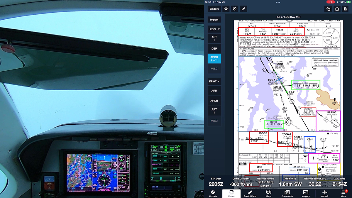
Unlike DME arcs, RF legs are defined by points in space, not distances from a ground-based transmitter. They can be strung together into sinuous paths, that, as noted above, provide lower minimums while avoiding obstacles, airspace conflicts, and noise-sensitive areas. The plan view from the RNAV (RNP) Z RWY 13R approach at Boeing Field in Seattle (KBFI) shows such RF legs.

image

You can find examples of RF legs in non-RNP approaches at Carlsbad, CA (KCRQ) and Ketchikan, AK (PAKT) [thanks to John D. Collins for those references]. Because of the restrictions placed on flying RF legs, however, those procedures are not currently available to typical IFR pilots. RF legs are also features of some RNAV instrument departure and arrival procedures (SIDs and STARs).

FAA includes RF legs in procedures assuming that an aircraft can follow the curved path with great precision, hence the detailed requirements spelled out in AC 90-101A, AC 90-105A, and AIM 5-4-18. Chief among those requirements are a flight director and/or a roll-steering autopilot, stipulations that rule out many, if not most, light general aviation aircraft.

The new Garmin study demonstrates, however, that:

Instrument-rated general aviation pilots are able to hand fly RF legs and meet the 0.5 nm 95% FTE [standard flight technical error]  target and RF leg altitude restrictions without the aid of a flight director or autopilot in Part 23 Category A and B aircraft that are either minimally equipped or technically advanced…All pilots demonstrated acceptable proficiency on both straight legs and RF legs. The increase in RF leg FTE over straight leg FTE can be expected to be about the same magnitude from a minimally equipped aircraft to a technically advanced aircraft.

In other words, pilots were able to remain well within the boundaries specified for an RF leg, whether flying a Cherokee equipped with just a Garmin 430W and basic instrumentation or a speedier Cessna 400 outfitted with Garmin’s latest G2000 integrated glass cockpit and autopilot. The pilots achieved this performance while hand-flying challenging procedures that incorporated multiple RF legs specifically designed to stress-test both the avionics and their flying skills. You can see diagrams of these special procedures in the Garmin report.

Based on the findings (described in great detail in the Garmin document), Garmin concludes that:

Garmin recommends FAA revise its installation and operational guidance for RF legs to make clear that applicants may obtain airworthiness approval for installations without flight director/autopilot. To preclude the need to demonstrate adequate FTE margin for aircraft flying RF legs at greater than 200 knots without flight director/autopilot, Garmin recommends FAA revise its installation and operational guidance for RF legs to allow applicants to utilize an Aircraft Flight Manual limitation that restricts flying RF legs to 200 knots or less.

Furthermore, the study showed that a moving map, while a great benefit to situational awareness, isn’t necessary to fly RF legs accurately:

As this project has shown, FTE is decreased when a moving map is available and is thus consistent with the MLS curved path study conclusion that led to the FAA installation and operational guidance that “an aircraft must have an electronic map display depicting … RF legs.” However, this project has also clearly shown that a moving map is not required to maintain acceptable RF leg FTE, even during complex procedures and missed approaches.

The executive summary of the Garmin report outlines additional conclusions and recommendations that address specific issues related to flying RF legs in typical light GA aircraft.

The FAA isn’t saying when or if it will adopt the recommendations in Garmin’s report. So far, the agency has said only:

This demonstration project has shown early success and will continue with more flight testing and data collection.

But the well-designed study and detailed analysis suggest that many more pilots may in future be able to take advantage of some advanced RNP procedures, if the FAA agrees with the recommendations and avionics manufacturers and database providers include RF legs in future updates to the WAAS units now common in light GA aircraft.

Garmin released system software 6.11 for the GTN series on March 1, 2016. That update includes the ability to fly RF legs on approaches that are not classified as Authorization Required procedures. For more information, see also AC 90-105A.

Update on WAAS Approaches from FAA

By the end of 2016, every runway in the U.S. that qualifies for an approach with LPV minimums will have one. According to the fall 2012 edition (PDF) of SatNavNews, published by FAA:

The agency intends to publish another 2,500 procedures by 2016, which will allow every runway in the nation that qualifies for an LPV to have one.

The latest data available from FAA, as of September 20, 2012, show the total number of approaches with LPV minimums has reached 2,989. By comparison, there were 1,281 category 1 ILS approaches in the inventory as of that date. More than 50 percent of the so-called LPV approaches serve airports that have no approaches that rely on ground-based navigation aids (i.e., ILS, localizer, VOR, or NDB). LPV procedures truly are expanding the options for instrument-rated pilots who fly aircraft equipped with IFR-approved, WAAS-capable GPS navigators.

LPV approaches can serve runways that may not meet the requirements for an ILS–indeed, many of those runways are suitable only for small general aviation aircraft. To learn about some of the criteria, see Table K-1. Criteria to Support Instrument Flight Procedure Development and the associated notes (from AC 150/5300). For example, the minimum runway length for an LPV approach is usually 3200 feet; the comparable number for an ILS is 4200 feet.

AC 150-Table K-1

Now, the minimums for an LPV approach to a 3200-ft runway are at least 1 statute mile visibility and a DA of 350-400 feet. If an LPV procedure is to match the best minimums for a typical ILS (1/2 statute mile visibility and a DA of 200 feet), the LPV procedure must be to a runway that meets criteria for a conventional precision approach, including runway length, lighting, parallel taxiways, and markings.

For more details about the runway requirements for non-precision and precision approaches, see sections 2.6.4.2, 2.6.4.3, and 2.6.4.3 in AC 150/3500.

2.6.4.2 Non-Precision Approach (NPA).

An NPA is an instrument approach based on a navigation system that provides course deviation information, but no glidepath deviation information. NPA runways:
1. Support IFR approach operations to visibilities of ½ statute mile (0.8 km) or greater and have a HAT no lower than 250 feet (76 m).
2. Rely on NAVAIDs providing lateral only guidance for instrument approaches such as Very High Frequency Omnidirectional Range (VOR), non-directional beacon (NDB), Area Navigation (RNAV) Lateral Navigation (LNAV), localizer performance (LP), and localizer (LOC).
3. Generally, have lengths at least 3,200 feet (975 m) long, with a minimum width based on RDC.
4. Have runway edge lights using LIRL or MIRL.
5. Have non-precision runway markings, as defined in AC 150/5340-1.

2.6.4.2 Approach Procedure with Vertical Guidance (APV).

APV is an instrument approach based on a navigation system that is not required to meet the PA standards of the ICAO Annex 10, but that provides course and glidepath deviation information. Runways classified as APV handle instrument approach operations where the navigation system provides vertical guidance down to 200 feet (61 m) HAT and visibilities to as low as ½ statute mile (0.8 km). APV runways:
1. May apply to the following approach types: Vertical Navigation (VNAV), Localizer Performance with Vertical Guidance (LPV), or RNAV/Required Navigation Performance (RNP).
2. Typically have a length of at least 3,200 feet (975 m) in length and a typical width of at least 60 feet (18.3 m).

2.6.4.3 Precision Approach (PA).

A PA is an instrument approach based on a navigation system that provides course and glidepath deviation information. Runways classified as precision, handle instrument approach operations supporting an instrument approach with a HAT lower than 250 feet (76 m) and visibility lower than ¾ statute mile (1.2 km), down to and including Category (CAT) III. Precision Instrument Runways (PIRs):
1. Support IFR operations with visibilities down to and including CAT-III with the appropriate infrastructure.
2. Have navigational systems capable of supporting precision operations that include instrument landing system (ILS) and Ground Based Augmentation System (GBAS) Landing System (GLS). (FAA Order JO 6850.2 contains descriptions of various approach lighting systems.)
3. Have runway lengths of at least 4,200 feet (1280 m).
4. Have minimum runway width of at least 75 feet (22.9 m) with the typical width being 100 feet (30.5 m).
5. Have High Intensity Runway Lights (HIRL).
6. Have precision runway markings, as defined in AC 150/5340-1.

Of course, an LPV procedure is essentially just data in a GPS navigator. To establish an LPV procedures, the owners of an airport don’t have to invest in or maintain ILS transmitters. Once the FAA has the required obstacle surveys and gathered related information, publishing LPV procedures to both ends of an eligible runway (indeed, to the ends of all eligible runways at an airport) requires little incremental investment (for example, to cover the costs of designing and flight-testing each additional procedure). That’s the main reason that the FAA can publish so many new LPV procedures and plan to meet the goal, in four years, of making LPV approaches available to all eligible runways.

RNP Procedures and Typical Part 91 Pilots

Some pilots remain confused about GPS-based RNAV approaches, especially procedures with RNP (Required Navigation Performance) in the title and AUTHORIZATION REQUIRED (AR) notes on the chart. For many reasons, those approaches (now called RNP AR procedures) are currently off-limits to a typical IFR pilot flying an airplane equipped with a WAAS-capable, IFR-approved GPS.

FAA is preparing a new Advisory Circular that addresses some of the issues discussed in this post. For more information about AC 90-119, see Draft AC 90-119 Performance-Based Navigation Operations.

The situation is becoming more complicated with the publication of RNAV approaches such as the RNAV (GPS) X RWY 24 at KCRQ (see below). Although that procedure is not labeled RNP AR, one transition (from VISTA) includes an RF (radius-to-fix) leg, a curved path that resembles a DME arc, but which requires specific equipment to fly–see below. Many of us flying with GPS units like the Garmin GNS400/500W  navigators may not see this procedure in the database, but it may appear among the updated charts you receive from Jeppesen or FAA AeroNav Products.

Garmin released system software 6.11 for the GTN series on March 1, 2016. That update includes the ability to fly RF legs on approaches that are not classified as Authorization Required procedures. For more information, see Garmin GTN Avionics and RF Legs here at BruceAir.

image

For a basic explanation of why you need specific authorization to fly RNP AR procedures, see the Instrument Procedures Handbook:

In the United States, operators who seek to take advantage of [RNP AR] approach procedures must meet the special RNP requirements outlined in FAA [AC 90-101A], Approval Guidance for RNP Procedures with Authorization Required (AR). Currently, most new transport category airplanes receive an airworthiness approval for RNP operations. However, differences can exist in the level of precision that each system is qualified to meet. Each individual operator is responsible for obtaining the necessary approval and authorization to use these instrument flight procedures with navigation databases. (4-30)

AC 90-101A explains in part:

a. RNP AR approaches include unique capabilities that require special aircraft and aircrew authorization similar to Category (CAT) II/III instrument landing system (ILS) operations. All RNP AR approaches have reduced lateral obstacle evaluation areas and vertical obstacle clearance surfaces predicated on the aircraft and aircrew performance requirements of this AC. In addition, selected procedures may require the capability to fly an RF leg and/or a missed approach, which requires RNP less than 1.0. Appendix 2 of this AC identifies specific aircraft requirements that apply to these capabilities.

A more detailed description of an RNP procedure from AC 90-101A, helps you understand why a typical WAAS-capable piston flown by a single pilot doesn’t qualify:

2. Characteristics of RNP AR Approaches.a. RNP Value. Each published line of minima has an associated RNP value. For example, Figure 2 shows both RNP 0.3 and RNP 0.15 lines of minima. Each operator’s RNP AR authorization documents a minimum RNP value, and this value may vary depending on aircraft configuration or operational procedures (e.g., use of flight director (FD) with or without autopilot). RNP AR approaches will have an RNP value of RNP 0.3 or less.

b. Procedures with Radius to Fix (RF) Legs. Some RNP AR approaches include RF legs. The instrument approach charts will indicate requirements for RF legs in the notes section or at the applicable initial approach fix (IAF). Figures 1 and 2 provide examples of procedures with an RF leg segment (e.g., between SKYKO and CATMI).

[Note that the presence of RF legs alone no longer automatically classifies an approach as an RNP AR procedure. For more information, see AC 90-105A and the updated Pilot’s Guide and other documentation related to the March 1, 2016 update of the system software for the Garmin GTN series navigators. More details are also available at Garmin GTN Avionics and RF Legs here at BruceAir].

c. Missed Approaches Requiring Less Than RNP 1.0. At certain locations, the airspace or obstacle environment may require RNP capability of less than 1.0 during a missed approach. Operation on these approaches typically requires redundant equipment. This requirement ensures that no single point of failure can cause loss of RNP capability. Figure 2 provides an example of a missed approach requiring RNP less than 1.0. The notes section of the chart indicates this requirement.

d. Non-Standard Speeds or Climb Gradients. Normally, RNP AR approach procedure design relies on standard approach speeds and climb gradients including on the Missed Approach Segment (MAS). The approach procedure will indicate any exceptions to these standards, and the operator must ensure it can comply with any published restrictions before conducting these approach operations. Figure 2 provides an example of a non-standard climb gradient and speed restrictions.

AC 90-101A also describes the training necessary for crews authorized to fly RNP AR procedures and the equipment requirements (beyond a WAAS-capable GPS receiver) necessary to fly those approaches.

With all that in mind, it’s important to understand that if your airplane is equipped with, say, a GNS530W or one of the new GTN boxes (with an appropriate AFM supplement), you can fly RNAV SIDs and STARs based on RNP-1 criteria. And you can, of course, fly en route segments that require RNP-2 accuracy. No special authorization is required at these RNP levels. For an explanation of RNP levels, see “Required Navigation Performance” in the Instrument Procedures Handbook (2-34).

AC 90-105A, published in March 2016, revises some of the terminology associated with RNAV and RNP procedures, in part to bring FAA conventions into agreement with ICAO standards associated with performance based navigation (PBN). The AC describes Required Navigation Performance Approach (RNP APCH) procedures, which you should not confuse with RNP AR procedures. RNP APCH is essentially equivalent to RNAV (GPS). If you fly with an IFR-approved GPS, your aircraft meets the requirements to fly basic RNP APCH procedures as described in the AC. But you can’t fly RNP AR procedures unless you also meet the requirements of AC 90-101A.

image

For more information about operations approved for different IFR-approved GPS units, see AC 90-100A, “U.S. Terminal and En Route Area Navigation (RNAV) Operations,” and the associated AC 90-100A Compliance Table. A good summary of AC 90-100A is available here.

To learn more about the capabilities of Garmin panel-mount avionics, including the various G1000 and GTN-series products, see Garmin Performance-Based Navigation Capabilities (PDF), a brochure published by Garmin.

Additional details about PBN are at the FAA website here.

Use of Suitable Area Navigation (RNAV) Systems on Conventional Procedures and Routes

I often get questions about how and when a pilot can substitute a GPS receiver/navigator for ground-based navigation aids when flying under IFR.

For a detailed discussion of this topic, see my presentation: Using GPS on Conventional Procedures.

Fortunately, an update to the AIM (dated 25 August 2011) included revisions to section 1-2-3: Use of Suitable Area Navigation (RNAV) Systems on Conventional Procedures and Routes, specifically to clarify the use of RNAV systems (especially IFR-approved GPS units) as substitutes for ground-based navaids.

For information about a further change to this section of the AIM in 2016, see
Use of IFR GPS on Conventional Approaches and Use of GPS on Conventional Approaches (Update) at BruceAir. And for additional suggestions, see Setting the CDI on a Conventional Approach (The “Kill Switch”).

Note 1 of that section also explains that “Additional information and associated requirements are available in Advisory Circular 90-108 titled ‘Use of Suitable RNAV Systems on Conventional Routes and Procedures.'”

New AIM section 1-2-3 explains that:

…b. Types of RNAV Systems that Qualify as a Suitable RNAV System. When installed in accordance with appropriate airworthiness installation requirements and operated in accordance with applicable operational guidance (e.g., aircraft flight manual and Advisory Circular material), the following systems qualify as a suitable RNAV system:

1. An RNAV system with TSO-C129/ -C145/-C146 equipment, installed in accordance with AC 20-138, Airworthiness Approval of Global Positioning System (GPS) Navigation Equipment for Use as a VFR and IFR Supplemental Navigation System, or AC 20-130A, Airworthiness Approval of Navigation or Flight Management Systems Integrating Multiple Navigation Sensors, and authorized for instrument flight rules (IFR) en route and terminal operations (including those systems previously qualified for “GPS in lieu of ADF or DME” operations), or

2. An RNAV system with DME/DME/IRU inputs that is compliant with the equipment provisions of AC 90-100A, U.S. Terminal and En Route Area Navigation (RNAV) Operations, for RNAV routes. A table of compliant equipment is available [here] (Microsoft Excel worksheet. That worksheet lists details about the specific capabilities of various units (subject, of course, to any limitations in the AFM supplement for your aircraft).

For most GA pilots, only item 1 applies. “RNAV system with TSO-C129/ -C145/-C146 equipment…” basically means IFR-approved GPS units, either non-WAAS or WAAS-capable boxes.

The updated language in the AIM includes the following explanations:

Uses of Suitable RNAV Systems. Subject to the operating requirements, operators may use a suitable RNAV system in the following ways:

1. Determine aircraft position relative to, or distance from a VOR (see NOTE 5 below), TACAN, NDB, compass locator, DME fix; or a named fix defined by a VOR radial, TACAN course, NDB bearing, or compass locator bearing intersecting a VOR or localizer course.

2. Navigate to or from a VOR, TACAN, NDB, or compass locator.

3. Hold over a VOR, TACAN, NDB, compass locator, or DME fix.

4. Fly an arc based upon DME.

NOTE-
1. The allowances described in this section apply even when a facility is identified as required on a procedure (for example, “Note ADF required”).

2. These operations do not include lateral navigation on localizer-based courses (including localizer back-course guidance) without reference to raw localizer data.

3. Unless otherwise specified, a suitable RNAV system cannot be used for navigation on procedures that are identified as not authorized (“NA”) without exception by a NOTAM. For example, an operator may not use a RNAV system to navigate on a procedure affected by an expired or unsatisfactory flight inspection, or a procedure that is based upon a recently decommissioned NAVAID.

4. Pilots may not substitute for the NAVAID (for example, a VOR or NDB) providing lateral guidance for the final approach segment. This restriction does not refer to instrument approach procedures with “or GPS” in the title when using GPS or WAAS. These allowances do not apply to procedures that are identified as not authorized (NA) without exception by a NOTAM, as other conditions may still exist and result in a procedure not being available. For example, these allowances do not apply to a procedure associated with an expired or unsatisfactory flight inspection, or is based upon a recently decommissioned NAVAID.

5.  For the purpose of paragraph c, “VOR” includes VOR, VOR/DME, and VORTAC facilities and “compass locator” includes locator outer marker and locator middle marker.

I also have links to several useful resources about GPS and WAAS on my Aviation Resources page.

Another reason for WAAS: New approach at Petaluma, CA (O69)

The latest batch of Jepp revisions just arrived. They include a new RNAV (GPS) RWY 29 approach at Petaluma, CA (O69).* (According to NACO, the RNAV approach was published on 25 August, but for some reason, it didn’t show up in my Jepps until now.)

The new RNAV approach has LPV minimums [DA 347 (270) and 7/8 sm] and an LNAV MDA of 820 (743) with visibility minimums of 1 (A) and 1-1/4 (B) miles.**

Previously, O69 had a VOR RWY 29 approach off SGD with an MDA of 1260 (1174) and 1-1/4 sm required visibility. The old GPS approach to the same runway offered an MDA of 900 (813) and 1 sm visiblity. And that GPS approach (now NA) had a 22-degree dogleg at the FAF.

The new approach is a significant improvement that shows the value of WAAS-based procedures, even to a 3600-ft runway, and it allows you to file O69 as an alternate if you have WAAS.

Here are links to the NACO versions of the new charts:

N.B. that the VOR RWY 29 procedure, updated for a new airport elevation, etc., still has a note that requires using the Santa Rosa altimeter setting, otherwise, the approach is NA. But the RNAV RWY 29 approach takes advantage of the on-field AWOS, and local weather is required for filing O69 as an alternate. I’m betting someone at FAA neglected to remove the Santa Rosa altimeter requirement for the VOR approach.

*The airport has an AWOS-3PT (AWOS-3PT contains all the AWOS-3 sensors, plus a precipitation identification sensor and thunderstorm detector). Phone: 707-773-1529.

**The new RNAV approach includes LNAV/VNAV mins–484 (707) and 1-3/8 sm–but if you’re using WAAS and the satellite configuration is good enough for vertical guidance, you’ll almost certainly see LPV annunciated, not LNAV/VNAV.