RNP: Performance Monitoring in Light GA Aircraft

The discussion of RNP–Required Navigation Performance– in AIM 1−2−2. Required Navigation Performance (RNP) and other FAA guidance confuses many pilots because the usual definition of RNP focuses on the type of equipment typically installed in bizets and airliners, not light GA aircraft.

Here are the key sentences in that AIM description of RNP:

RNP is RNAV with the added requirement for onboard performance monitoring and alerting (OBPMA). RNP is also a statement of navigation performance necessary for operation within a defined airspace. A critical component of RNP is the ability of the aircraft navigation system to monitor its achieved navigation performance, and to identify for the pilot whether the operational requirement is, or is not, being met during an operation. 

TBL 1-2-1 in the AIM shows the values, in nautical miles, associated with each standard RNP level.

Most GA pilots are concerned with only the RNP APCH (0.3 to 1.0), Terminal (1.0), and En Route (2.0) RNP levels.

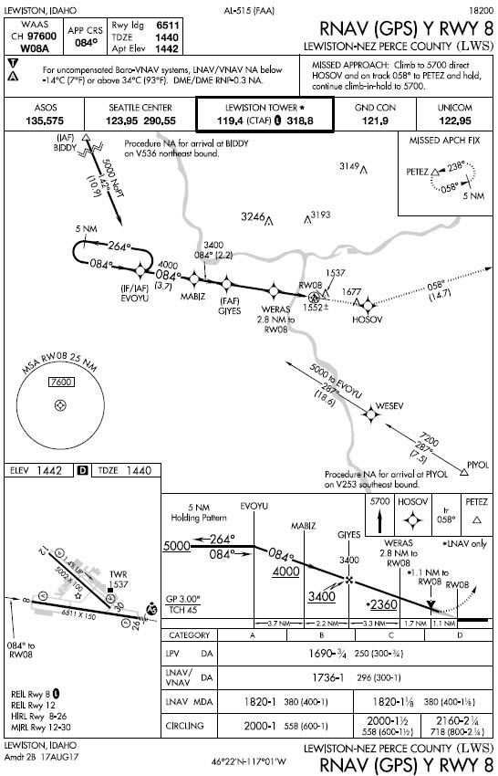
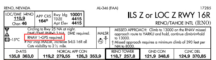
For more information about how RNP, RNAV, and related notes are used on IFR approach charts, see Unscrambling RNAV, RNP, and Other Chart Naming Conventions and Notes here at BruceAir.

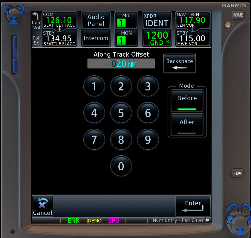
Unlike the FMS and other equipment in jets, the displays in the suitable RNAV systems (i.e., GPS and WAAS navigators) and PFDs installed in our aircraft usually don’t show numerical values for RNP levels. So how you verify that your system is achieving the required navigation performance during different phases of flight?

The avionics common the light GA world typically annunciate RNP status by displaying ENR, TERM, LNAV, LPV, LP, etc., as described in the tables below from the Garmin Pilot’s Guide for the GTN series (190-02327-03D).

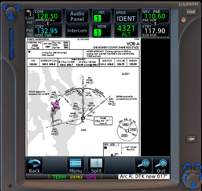
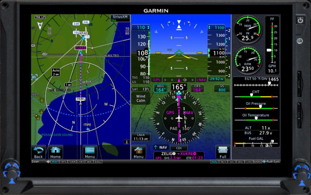
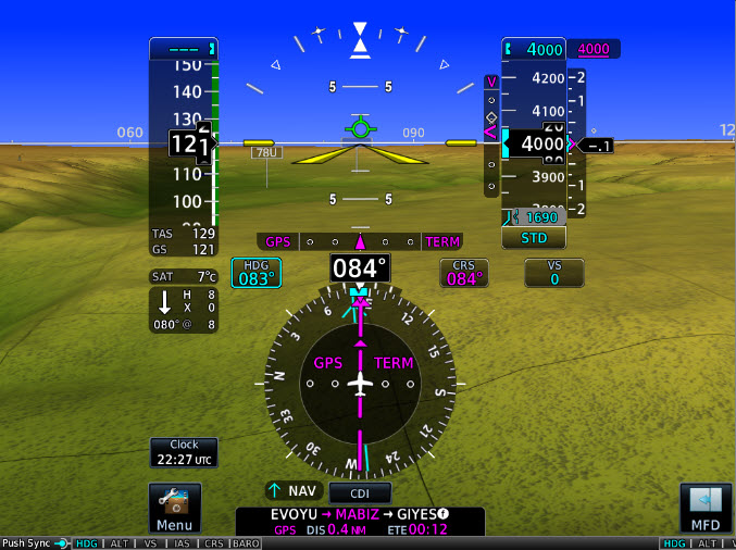
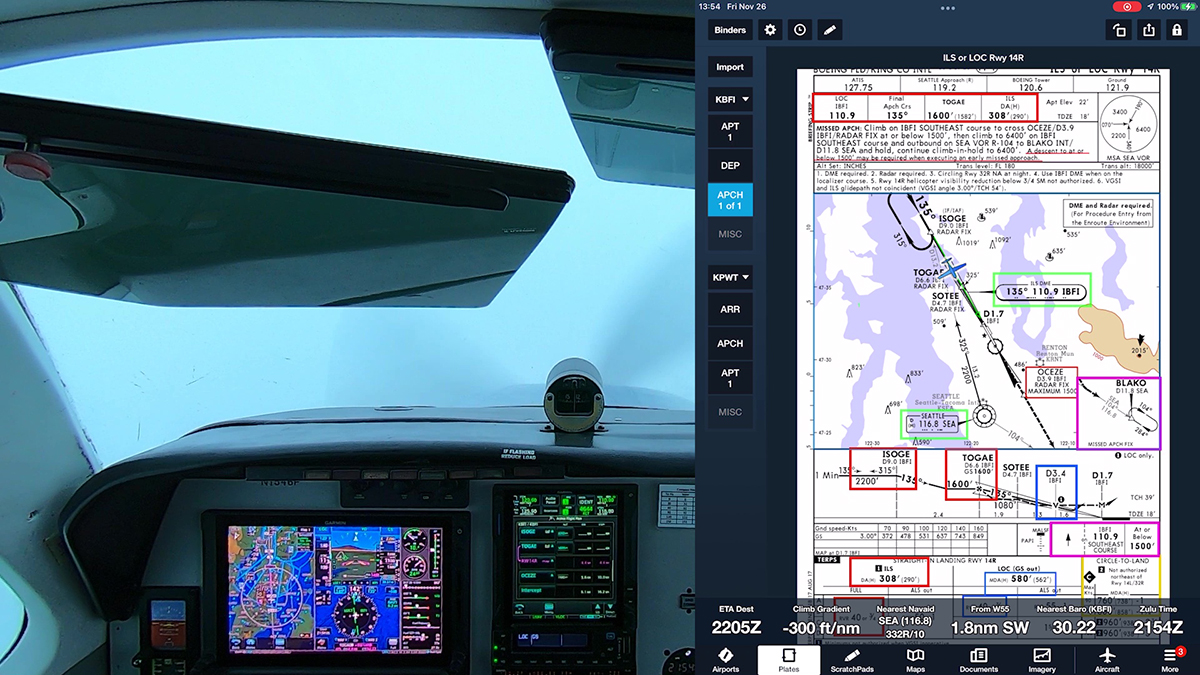
These letter-based RNP annunciations typically appear on the PFD near or within the HSI and on the screen for the navigator, as shown in the examples below.

A table below from the Pilot’s Guide for the Garmin G500 Txi (190-01717-10 Rev. J). provides similar information.

The LNAV, LNAV+V, LPV, LP, LP+V, and (rarely LNAV/VNAV or L/VNAV) annunciations are associated with the RNP APCH level, which is 0.3 nm for basic lateral navigation and is also used for the tighter, angular courses defined for the localizer-like final approach segments established for approaches with LPV and LP minimums.

FAA is preparing a new advisory circular, AC 90-119, which should consolidate and clarify guidance about performance-based navigation (PBN), RNAV, RNP, and related topics in one document. I submitted comments asking that tables like those above be included in the sections that define RNP values and explain how typical GA pilots can meet the requirement to monitor RNP while operating under IFR.

For a detailed look at the draft of the new AC and to see my comments, see Draft AC 90-119 Performance-Based Navigation Operations here at BruceAir.

Unscrambling RNAV, RNP, and Other Chart Naming Conventions and Notes

Many pilots are confused by the terms RNAV, RNP, and RNP APCH that appear on instrument approach charts, and it’s easy to see why.

Although ICAO is adopting a new naming standard as the world shifts to Performance Based Navigation, or PBN, the FAA is sticking to its conventions. And that approach leads to some terms having more than one meaning or to blurring important distinctions.

This video below takes a closer look at what those abbreviations, initialisms, and notes mean.

You can watch videos on other topics at my Presentations for Pilots playlist on YouTube.

For more information on this topic, see:

VOR Approaches with LNAV+V

Thanks to John Collins, an avionics expert and colleague of mine, I recently learned about feature that Garmin seems to have added to the GTN Xi series navigators and the G500/600 TXi flight displays.

Update: This feature is now documented in the latest GTN 750Xi Pilot Guide (190-02327-03 Rev. D). VOR+V Approaches (p. 3-135) explains that:

Per guidance provided in AC 90-108 regarding the use of GPS as an alternate means of navigation, VOR and NDB approaches may be treated as LNAV+V approaches (i.e., LNAV with advisory vertical guidance) as long as the pilot monitors the VOR.

During approach selection, “+V” displays for VOR and NDB approaches when advisory guidance is available. Approach strings remain unmodified when no vertical guidance is available.

If the approach indicates “VOR+V,” then advisory vertical guidance may be removed without indication. This is due to the vertical guidance not being within tolerances. This does not constitute a downgrade. You may still fly the approach to VOR minimums. Flying a VOR approach with advisory vertical guidance (VOR+V) does not change how the approach should be flown. The pilot is still responsible for descending to the correct altitude at each step down. The result is still an MDA and missed approach point.

FAA updated the AIM and other guidance a few years ago to allow you to “fly the magenta line” along the final approach course of a VOR or NDB approach, if the navaid is working and you can monitor the course with a CDI or bearing pointer.

Note that with GTN Xi software version 20.30 and later, descriptions of VOR/DME, VOR, NDB/DME, NDB, and TACAN approaches with advisory vertical guidance now show “+V” instead of “LNAV+V.”

I’ve explained the details and shown examples of this technique in several posts here at my blog and in a video presentation and a webinar about using GPS while flying conventional procedures and routes:

But now the Garmin GTN Xi units, and I assume their siblings, the GTX and latest GPS navigators, have added advisory vertical guidance, even to VOR approaches. To my knowledge, this feature hasn’t been documented in Garmin manuals or other sources, and it’s not clear to me which minimum hardware and software combinations support this feature.

To test the feature on a fine VFR day in an airplane, I hopped from Boeing Field (KBFI) in Seattle to nearly Olympia, WA (KOLM) to fly the VOR RWY 35 approach.

Ride along with me in this video to see this feature in action.

AIM Update: Approach Categories

FAA has released the January 30, 2020 update to the AIM. (Link to PDF and HTML editions here. You can read the explanation of changes here.)

The update includes several items of interest to IFR pilots, but one is of particular note here:

5−4−7. Instrument Approach Procedures
This change provides pilots with additional options when it is necessary to conduct an instrument approach at an airspeed higher than the maximum airspeed of its certificated aircraft approach category. It explains the flexibility provided in 14 CFR and emphasizes the primary safety issue of staying within protected areas.

Here’s the new text in that section:

a. Aircraft approach category means a grouping of aircraft based on a speed of Vref at the maximum certified landing weight, if specified, or if Vref is not specified, 1.3Vso at the maximum certified landing weight. Vref, Vso, and the maximum certified landing weight are those values as established for the aircraft by the certification authority of the country of registry. A pilot must maneuver the aircraft within the circling approach protected area (see FIG 5−4−29) to achieve the obstacle and terrain clearances provided by procedure design criteria.

b. In addition to pilot techniques for maneuvering, one acceptable method to reduce the risk of flying out of the circling approach protected area is to use either the minima corresponding to the category determined during certification or minima associated with a higher category. Helicopters may use Category A minima. If it is necessary to operate at a speed in excess of the upper limit of the speed range for an aircraft’s category, the minimums for the higher category should be used. This may occur with certain aircraft types operating in heavy/gusty wind, icing, or non−normal conditions. For example, an airplane which fits into Category B, but is circling to land at a speed of 145 knots, should use the approach Category D minimums. As an additional example, a Category A airplane (or helicopter) which is operating at 130 knots on a straight−in approach should use the approach Category C minimums.

c. A pilot who chooses an alternative method when it is necessary to maneuver at a speed that exceeds the category speed limit (for example, where higher category minimums are not published) should consider the following factors that can significantly affect the actual ground track flown:

1. Bank angle. For example, at 165 knots ground speed, the radius of turn increases from 4,194 feet using 30 degrees of bank to 6,654 feet when using 20 degrees of bank. When using a shallower bank angle, it may be necessary to modify the flight path or indicated airspeed to remain within the circling approach protected area. Pilots should be aware that excessive bank angle can lead to a loss of aircraft control.

2. Indicated airspeed. Procedure design criteria typically utilize the highest speed for a particular category. If a pilot chooses to operate at a higher speed, other factors should be modified to ensure that the aircraft remains within the circling approach protected area.

3. Wind speed and direction. For example, it is not uncommon to maneuver the aircraft to a downwind leg where the ground speed will be considerably higher than the indicated airspeed. Pilots must carefully plan the initiation of all turns to ensure that the aircraft remains within the circling approach protected area.

4. Pilot technique. Pilots frequently have many options with regard to flight path when conducting circling approaches. Sound planning and judgment are vital to proper execution. The lateral and vertical path to be flown should be carefully considered using current weather and terrain information to ensure that the aircraft remains within the circling approach protected area.

The Runway Environment in the RNAV Era

As of January 30, 2020, the FAA had published 4,048 RNAV (GPS) approaches with LPV (localizer performance with vertical guidance) minimums at 1,954 airports; 1,186 of those airports are not served by an ILS. The number of LPV-capable procedures is almost three times the 1,550 approaches with Category I ILS minimums, and 2,838 of the procedures with LPV minimums serve runways without an ILS,

For the latest totals, visit the Instrument Flight Procedures (IFP) Inventory Summary and Satellite Navigation — GPS/WAAS Approaches pages at the the FAA website.

FAA.gov

This capability to fly ILS-like procedures to thousands of runways at small-town and rural airports is a boon to IFR pilots. But you must carefully prepare to fly approaches to runways that don’t have the ground infrastructure associated with an ILS–most importantly an approach lighting system and accessories such centerline and touchdown zone lighting. And keep in mind that a non-ILS runway may not be as a long as you’re accustomed to–the minimum length for a runway served by an approach with LPV minimums is just 3200 ft. (more details here).

For more information about GPS-based approaches, see Required Navigation Performance (RNP) Approaches (APCH) .

FAA.gov

For example, here’s video of the final approach segment of the RNAV (GPS) RWY 16 procedure at Chehalis, WA (KCLS) during a night approach.

As the video shows, the runway can be hard to spot. It has REILs and a PAPI, but it’s in a dark area near a river. And you must remember to activate the lights by clicking the transmit button on the CTAF as you approach the airport. (The camera makes the scene look a little darker than it really was to human eyes–but you get the idea.)

Chehalis (KCLS) airport

That approach has an LPV decision altitude of 476 ft MSL (300 ft. AGL). The visibility requirement is 1 sm. That’s not much greater than the 200 ft DA and 1/2 sm visibility for a typical Category 1 ILS. But the environment is vastly different than that presented by an ILS runway with its bright lights and other big-city features.

Here’s an overview of the approach lighting systems associated with ILS procedures.

Instrument Procedures Handbook:
Figure 9-36. Precision and nonprecision ALS configuration.

Contrast the view at KCLS with the scene at Boeing Field (KBFI) in Seattle during the final stages of an ILS approach.

ILS RWY 14R at Boeing Field (KBFI)

Here’s an approach to runway 20 at Bremerton, WA (KPWT). KPWT is a non-towered airport, but runway 20 is served by an ILS approach, which includes an ALS.

KPWT
RNAV RWY 20 approach at KPWT

So, regardless of the type of approach you’re flying, make sure you review and prepare for the runway environment that you’ll encounter when you break out of the clouds and go visual. It’s especially important to know which of the visual cues described by 14 CFR §91.175 Takeoff and landing under IFR will be available.

KSHN RNAV (GPS) RWY 23

Here’s video from a recent IFR proficiency flight in my Beechcraft A36, a 1989 model with updated avionics, including a Garmin G500 PFD/MFD and Garmin GTN 750.

Video of an approach at KSHN

I departed Boeing Field (KBFI) in Seattle for the quick hop to Sanderson Field in Shelton, WA (KSHN).

The basic route on a VFR chart

This video picks up after Seattle Approach cleared me to HOOME, an IAF for the RNAV (GPS) RWY 23 approach.

My avionics are capable of flying this procedure to LPV (localizer performance with vertical guidance) minimums. In other words, this RNAV (GPS) procedure offers approved vertical guidance–a GPS-derived glidepath. Flying to LPV minimums effectively uses the same techniques as flying an ILS.

Note, however, that this procedure includes two lines of LPV minimums. The decision altitude (DA) for the first line is 523 ft with a visibility requirement of 3/4 sm.

The second LPV line has higher minimums: 667 ft and 1-1/4 sm.

Why the difference? Note the # next to the DA in the first line. It leads you to a note in the description near the top of the chart:

#LPV missed approach requires minimum climb of 244 feet per NM to 1700.

To use the minimums of DA of 523 and 3/4 sm visibility, you must be able to climb at 244 feet per NM during the initial stages of the missed approach. That’s a slightly higher climb gradient than the standard 200 feet per NM.

Note that the climb requirement is for a climb gradient in feet per NM, not a rate of climb in feet per minute. To determine if your aicraft is capable of achieving the required climb gradient, you must check the Climb/Descent Table in the supplement to the Terminal Procedures Publication or calculate the climb gradient that corresponds to your groundspeed and rate of climb when you fly the missed approach portion of the procedure.

In my A36, climbing out at 110 KIAS, with a groundspeed of about 100 KIAS given the headwind component, and an initial (conservative) climb rate of about 600 fpm, my climb gradient is about 300 ft/nm, so I can use the lower DA and visibility when flying this approach.

You can find more videos from this IFR flight at my YouTube channel, BruceAirFlying.

Use of GPS on Conventional Approaches (Update)

Users of Garmin GTN and GNS navigators may now use the GPS CDI as an alternate means of guidance along the final approach course of a VOR or NDB approach, provided they monitor the ground-based navaid to ensure that they’re tracking the proper final approach course. Previous editions of the AFM supplement for GTN and GNS avionics required you to display the VOR CDI on your HSI or PFD even if you could monitor the ground-based navaid on a separate CDI or by using a bearing pointer.

Note that you must still display the VOR/LOC (“green needles”) CDI to fly the final approach segment of an approach based on a localizer or any other type of navaid except a VOR or NDB.

For more information about setting the CDI while flying approaches, see
Setting the CDI on a Conventional Approach (The “Kill Switch”). For general background, see Use of Suitable Area Navigation (RNAV) Systems on Conventional Procedures and Routes

The updated language in the AFM supplement for the GTN and GNS series (see below) synchronizes the limitations in the AFM supplement with a 2016 update to AIM 1−2−3. Use of Suitable Area Navigation (RNAV) Systems on Conventional Procedures and Routes (see Use of IFR GPS on Conventional Approaches).

In March 2020, Garmin also updated the AFM supplements for the GNS 530W and GNS 430W to reflect this change. See the 190-00357-03_g version of that document, available at the Garmin website.

The change came with a recent update to the system software for the GTN line of GPS navigators (more information about the new features at BruceAir here).

The new software brings a significant change to the language in the approved Airplane Flight Manual Supplement for the GTN boxes (the PDF of the new AFM supplement for the GTN 750 is available here).

Section 2.10 Instrument Approaches in that AFM supplement now notes the following:

…c) The navigation equipment required to join and fly an instrument approach procedure is indicated by the title of the procedure and notes on the IAP chart. Navigating the final approach segment (that segment from the final approach fix to the missed approach point) of an ILS, LOC, LOC-BC, LDA, SDF, MLS, VOR, TACAN approach, or any other type of approach not approved for GPS, is not authorized with GPS navigation guidance. GPS guidance can only be used for approach procedures with GPS or RNAV in the procedure title. When using the Garmin LOC/GS receivers to fly the final approach segment, LOC/GS navigation data must be selected and presented on the CDI of the pilot flying. When using the VOR or ADF receiver to fly the final approach segment of a VOR or NDB approach, GPS may be the selected navigation source so long as the VOR or NDB station is operational and the signal is monitored for final approach segment alignment. [Emphasis added]

A test of the new software in the free Garmin PC-based trainer indicates that the message warning the pilot to switch the CDI from GPS to VOR has also been removed. The following captures show the VOR-A approach at Paine Field (KPAE) north of Seattle flown with the CDI with GPS selected. Note the cyan bearing pointer behind the magenta GPS CDI.KPAE-VOR-A-XUKRE-G500TXi.jpg

KPAE-VOR-A-ARC-GTN750
KPAE-VOR-A-ECEPO-G500TXi
KPAE-VOR-A-ECEPO-GTN750

New Garmin GTN 750 Features

Garmin has released system software 6.50 (since updated to 6.51, which is a mandatory update) for its GTN 750 and GTN 650 navigators. The new software adds several features, including:

  • Vertical navigation (VNAV) capability when flying STARS and the initial stages of instrument approaches
  • Along-track offsets in flight plan segments
  • Destination airport remains in the flight plan when an approach is loaded (but the destination airport is removed when the approach is activated)
  • A shortcut to the airport info page added to all procedure headers
  • Load the approach NAV frequency from the approach header in the flight plan
  • QWERTY keyboard option

The following sections highlight some of these features. For more details on how to use the functions, see the latest editions of the GTN guides, available in my Aviation Documents folder at OneDrive and from Garmin’s product pages.

The details about this update to the GTN series are in ASDN Service Bulletin 1860, the 6.51 mandatory udpate, and the GTN 725/750 SOFTWARE v6.50 PILOT’S GUIDE UPGRADE SUPPLEMENT.

Garmin also released system software updates for the G500/600 PFD/MFD and associated hardware. For details on those updates, see ASDN Service Bulletin 1861.

Garmin has also updated its free Windows-based trainer for the GTN series.

Note that these system updates must be performed by an authorized Garmin dealer or avionics shop unless you are flying a experimental-homebuilt aircraft.

VNAV Capability

The new software adds several vertical navigation features, best illustrated with examples.

Garmin has published a video that describes the VNAV feature in detail, here.

Suppose you are flying the RNAV RWY 08 approach at Lewiston, ID (KLWS), joining the procedure at the BIDDY initial approach fix northwest of the airport. The NoPT feeder route from BIDDY specifies an an altitude of at or above 5000 ft to EVOYU, followed by a descent to at or above 4000 ft to MABIZ, and then at or above 3400 ft to the FAF at GIYES.

KLWS-RNAV-RWY08

With the new GTN system software, those segment altitudes appear in the flight plan page for the procedure.

GTN750-KLWS-RNAV08-FltPlan-01
The VNAV feature appears as a magenta vertical guidance cue next to the altitude tape on a PFD such as the new Garmin G500Txi (shown here) or the G500. Note that at this point in the approach, the LPV glidepath is a dim white diamond behind the magenta VNAV cue because the FAF is not the active waypoint and LPV is not yet annunciated on the HSI.

The VNAV cue provides advisory guidance to help you smoothly descend to each charted altitude as you fly the initial stages of the approach.

GTN750-KLWS-RNAV08-TXi-01
The LPV glidepath marker that displays approved vertical guidance replaces the VNAV cue when the FAF is active and the GTN system confirms that LPV minimums are available, as shown below.

GTN750-KLWS-RNAV08-TXi-02

Similar VNAV information and cues are available when flying a STAR, such as the MADEE FOUR arrival at Bellingham, WA (KBLI).

KBL-MADEE-4

Note that the altitudes shown in the GTN flight plan list for this STAR are for turbojet aircraft. But you can easily edit the altitude if ATC assigns a more appropriate altitude when you’re flying a typical piston-powered light aircraft.

GTN750-KBLI-MADDEE-4-01

GTN750-KBLI-MADDEE-4-02

If you are flying an approach based on an ILS, LOC, or VOR, you can quickly retrieve the navaid frequency by touching the approach title, as shown below for the ILS RWY 16 at KBLI.

GTN750-KBLI-ILS-RWY16-01.jpg

Along-Track Offsets

Suppose you are flying northeast along V2 at 13,000 ft. between ELN and MWH when Seattle Center clears you to cross 20 nm west of MWH at 9000 ft.

IFR-Low-ELN-MWH.jpg

With the new software, you can easily enter an along-track offset and display advisory vertical guidance to help you meet the restriction.

Touch MWH in the flight plan, and then touch the new Along Track button.

GTN750-AlongTrack-ELN-MWH-01

To create a waypoint for VNAV guidance, fill in the information that corresponds to your new clearance.

GTN750-AlongTrack-ELN-MWH-02
GTN750-AlongTrack-ELN-MWH-03
GTN750-AlongTrack-ELN-MWH-04
GTN750-AlongTrack-ELN-MWH-05

Airport Information

An earlier version of the GTN system software included behavior that frustrated many pilots. When you loaded an approach into a flight plan, the destination airport was removed. If you hadn’t noted details such as the tower frequency, extracting that information from the GTN’s database was cumbersome.

In version 6.50, Garmin has added an APT Info button next to the approach title in the flight plan list.

GTN750-Procedure-AirportInfoButton-01

Touching that button shows the familiar information window that provides touch access to details about the airport, including frequencies, weather, and other data.

GTN750-Procedure-AirportInfoButton-02
QWERTY Keyboard

You can also choose a QWERTY keyboard instead of the alphabetical layout in previous versions of the GTN software. The option is available on the System Setup page.

GTN750-Qwerty-01
GTN750-Qwerty-02

An ILS that Requires GPS

You can still fly IFR in the U.S. without an IFR-approved GNSS (i.e., GPS), but being “slant G” (/G in the soon-to-be obsolete FAA domestic flight plan format) increasingly offers advantages, even if you fly only conventional procedures based on ground navaids. And sometimes an IFR-approved GNSS is required to fly even an ILS.

Other examples include the ILS or LOC RWY 28R at Billings, MT (KBIL) and the ILS or LOC RWY 12 at Huron, SD (KHON)

Consider the ILS Z OR LOC Z RWY 16R approach at Reno/Tahoe International Airport (KRNO). This procedure is not an Authorization Required approach–RNP doesn’t appear in the title, and you won’t find that restrictive note on the chart.

For more information about RNP procedures, see RNP Procedures and Typical Part 91 Pilots. To learn about new required equipment notes on FAA charts, see New Equipment Required Notes.

KRNO-ILSorLOCZRwy16R

But the equipment required notes for this ILS approach include “RNAV-1 GPS required.”

KRNO-ILSorLOCZRwy16R-notes
A review of the plan view and missed approach track show why GPS is necessary to fly this procedure.

KRNO-ILSorLOCZRwy16R-Plan

First, you need GPS to fly transitions from most of initial fixes, which are RNAV waypoints marked by a star symbol.

RNAV-Waypoint-Symbol

Only LIBGE, directly north of the runway, is a non-RNAV IAF.

For example, HOBOA, KLOCK, BELBE, and WINRZ are all RNAV waypoints that serve as IAFs or IFs. Now, NORCAL Approach might provide vectors to the final approach course, but if you want to fly this procedure you should be prepared for a clearance direct to one of those fixes (see Avoiding the Vectors-to-Final Scramble).

Note also that entire missed approach track requires use of GNSS.

Two of the transitions are of special note. The “arcs” that begin at ZONBI and SLABS are radius-to-fix (RF) legs that are part of the transitions that begin at HOBOA and KLOCK. Each of those fixes is distinguished by the notes “RNP-1 GPS REQD” and “RF REQD.”

The first note means that your GPS must meet the RNP 1 standard, which is used for terminal procedures such as SIDs and STARs, the initial phases of approaches, and missed-approach segments. (For more information about RNP, see RNP Procedures and Typical Part 91 Pilots.)

Until recently, RF legs were included only in Authorization Required (AR) procedures. But as I explained in Garmin GTN Avionics and RF Legs, certain RF legs are now available if you have an appropriate GNSS navigator, updated system software, an electronic HSI, and other equipment. Some limitations on flying such RFs also apply, as described in that earlier post.

Suppose that you choose the less intimidating ILS X or LOC X RWY 16R to the same runway. A review of the notes and the plan view shows that even this conventional-looking ILS also requires RNAV 1 GPS, both to fly the transition from WINRZ and the missed approach track.

KRNO-ILSorLOCXRwy16R.jpg

FAA Proposes Cuts to Circling Approach Minimums

The FAA has announced the early stages of plan to evaluate and then cut the number of circling minimums published for instrument approaches.

The FAA published its final criteria to guide the identification and selection of circling procedures that can be considered for cancellation on June 28, 2018. You can read the notice in the Federal Register here.

According to a notice in the Federal Register on October 6, 2017:

In early 2015, the FAA requested the RTCA’s Tactical Operations Committee (TOC) with providing feedback and recommendations on criteria and processes for cancelling instrument flight procedures. Among the many recommendations provided by the TOC were criteria on how to identify circling procedures that would qualify as candidates for cancellation. As of the beginning of 2017, there are approximately 12,000 IAPs in publication, and there were nearly 10,600 circling lines of minima. Circling procedures account for approximately one-third of all lines of minima in the NAS.

In its continued effort to right-size the NAS through optimization and elimination of redundant and unnecessary IAPs, the FAA proposes the following criteria to guide the identification and selection of appropriate circling procedures to be considered for cancellation…

Proposed Policy

All circling procedures will continue to be reviewed through the established IAP periodic review process.As part of that review process, the FAA is proposing that each circling procedure would be evaluated against the following questions:

—Is this the only IAP at the airport?

—Is this procedure a designated MON airport procedure?

—If multiple IAPs serve a single runway end, is this the lowest circling minima for that runway? Note: If the RNAV circling minima is not the lowest, but is within 50′ of the lowest, the FAA would give the RNAV preference.

—Would cancellation result in removal of circling minima from all conventional NAVAID procedures at an airport? Note: If circling minima exists for multiple Conventional NAVAID procedures, preference would be to retain ILS circling minima.

—Would cancellation result in all circling minima being removed from all airports within 20 NMs?

—Will removal eliminate lowest landing minima to an individual runway?

The following questions are applicable only to circling-only procedures:

—Does this circling-only procedure exist because of high terrain or an obstacle that makes a straight-in procedure unfeasible or which would result in the straight-in minimums being higher than the circling minima?

—Is this circling-only procedure (1) at an airport where not all runway ends have a straight-in IAP, and (2) does it have a Final Approach Course not aligned within 45 degrees of a runway which has a straight-in IAP?

Further consideration for cancellation under this policy would be terminated if any of the aforementioned questions are answered in the affirmative. If all questions are answered in the negative, the procedure would be processed as described in the following paragraph.