AIM Update June 17 2021

FAA has published the June 17, 2021 update of the Aeronautical Information Manual. You can download the PDF from the FAA website here.

Changes of interest to general aviation pilots in this update include:

4−1−11. DESIGNATED UNICOM/MULTICOM FREQUENCIES:

Over the Continental United States and Coastal Waters 123.4 MHz and 123.45 MHz are reserved by the Federal Communications Commission (FCC) for stations individually licensed to commercial aircraft and accessory manufacturers to use as flight test frequencies. Aircraft may only communicate with their associated company ground stations and these frequencies may not be used for air−to−air communications of any sort. In order to bring attention to the proper usage of 123.4 MHz and 123.45 MHz, this change adds these frequencies to TBL 4−1−3, Other Frequency Usage Designated by the FCC, along with the description of their use and the note that they are not for air−to−air communication.

Pilots have often informally used 123.4 (the so-called fingers) for formation flights and other air-to-air communications. This update makes it clear that the frequency isn’t to be used for that purpose.

7−1−5. PREFLIGHT BRIEFING
This change inserts language in the Aeronautical Information Manual that pilots do not need to call Flight Service in order to obtain a regulatory compliant briefing and encourages pilots to self−brief before calling a flight service station.

Use of IFR GPS on Conventional Approaches

FAA has published an update to the AIM, effective 26 May 2016, and it includes a big change if you have an IFR-approved GPS [i.e., a “suitable navigation system” as defined in AC 20-138 and AIM 1-2-3 (b).]

Now, if you fly a conventional approach based on a VOR or NDB (but not a localizer), you can fly the procedure entirely with the GPS, provided you can monitor (using a separate CDI or a bearing pointer) the VOR or NDB facility specified for the approach.

For more information about the use of GPS along the final approach course of a VOR or NDB approach, see Use of GPS on Conventional Approaches (Update)

If you prefer to switch the CDI to “green needles,” see Setting the CDI on a Conventional Approach (The “Kill Switch”) here at BruceAir.

The new language is in section 1−2−3. Use of Suitable Area Navigation (RNAV) Systems on Conventional Procedures and Routes.

The summary of changes to this AIM update notes that:

This change allows for the use of a suitable RNAV system as a means to navigate on the final approach segment of an instrument approach procedure (IAP) based on a VOR, TACAN, or NDB signal. The underlying NAVAID must be operational and monitored for the final segment course alignment.

The new text in the AIM is in paragraph 5 of AIM 1-2-3:

5. Use of a suitable RNAV system as a means to navigate on the final approach segment of an instrument approach procedure based on a VOR, TACAN or NDB signal, is allowable. The underlying NAVAID must be operational and the NAVAID monitored for final segment course alignment.

This change is the result of a discussion at the Aeronautical Charting Forum in 2014.

Changes in AIM Effective 26 May 2016

FAA has published an update to the AIM, effective 26 May 2016, and it includes several important changes of interest to typical general-aviation pilots:

1−2−3. Use of Suitable Area Navigation (RNAV) Systems on Conventional Procedures
and Routes

This change allows for the use of a suitable RNAV system as a means to navigate on the final approach segment of an instrument approach procedure (IAP) based on a VOR, TACAN, or NDB signal. The underlying NAVAID must be operational and monitored for the final segment course alignment. [For more information about this item, see the detailed discussion here.]

3−2−3. Class B Airspace
This change adds an RNAV Receiver as an option for instrument flight rule (IFR) navigation requirement IAW 91.131 (c)(1).

3−2−6. Class E Airspace

This change updates the definition, vertical limits, and types of Class E airspace. The change more accurately reflects Class E airspace regulatory information in 14 CFR Part 71 and more clearly states that Class E arrival extensions have the same effective times as the airport surface area airspace….

4−3−22. Option Approach
This changes adds verbiage advising pilots to inform air traffic control (ATC) as soon as possible of any delay clearing the runway during their stop−and−go or full stop landing.

5−2−8. Instrument Departure Procedures (DP) − Obstacle Departure Procedures (ODP) and Standard Instrument Departures (SID)
This change adds language advising pilots what to expect when vectored or cleared to deviate off of an SID.

5−4−1. Standard Terminal Arrival (STAR) Procedures
This change adds language advising pilots what to expect when vectored or cleared to deviate off of a STAR. Pilots should consider the STAR cancelled. If the clearance included crossing restrictions, controllers will issue an altitude to maintain. It also adds language advising pilots when to be prepared to resume the procedure. Since all clearances on STARS will not include Descend Via clearances, the word “will” was replaced with “may.”

5−4−7. Instrument Approach Procedures
This change adds a note to provide guidance to pilots regarding what to expect when clearances are issued by ATC to altitudes below those published on IAPs.

“The AIM is not Regulatory”

“The AIM is not regulatory” is an often-heard refrain among pilots and flight instructors. And technically, of course, that’s correct.

From the introduction to the Aeronautical Information Manual:

This publication, while not regulatory, provides information which reflects examples of operating techniques and procedures which may be requirements in other federal publications or regulations. It is made available solely to assist pilots in executing their responsibilities required by other publications.

However, when aviators say, “The AIM is not regulatory,” they generally seem to argue that the procedures and guidance in the AIM (and related FAA publications, such as advisory circulars), are suggestions that pilots, at their discretion, may adopt or ignore.

For a detailed discussion of the AIM and other advisory documents published by the FAA, see AIM Is Non-Regulatory, an article by Mark Kolber, an aviation attorney, published at AVweb in 2020.

I’m certainly not an attorney. But I offer this background on the authority of the AIM from AOPA Flight Training. That Legal Briefing (written by an attorney) notes in part:

…In older NTSB cases, both the FAA and the airman have used sections of the AIM to assess whether an airman’s conduct was in violation of the FAR or not. For example, an airman attempted to justify a right turn during his approach to the airport as part of a “straight-in” approach as set forth in the AIM. But the case did not rely on the new statutory language of deference.

In a more recent NTSB case involving a pilot’s misunderstood readback of an ATC instruction that ATC failed to correct and which resulted in an altitude deviation, the NTSB found that because the pilot acted as best he could to understand and comply with the ATC instruction, he could not be held responsible for the deviation. But the FAA appealed the NTSB’s decision to the Court of Appeals, which held that the NTSB must defer to the FAA’s interpretation that the pilot is responsible for accurately understanding and complying with an ATC instruction absent an equipment malfunction or an emergency. The court sent the case back to the NTSB, which then had to find the pilot in violation.

These cases suggest that you may be held responsible for complying with FAA guidance. Or, you could find yourself defending against an interpretation of a regulation that the FAA announces, for the first time, in response to your conduct. In any event, while it may not be a regulatory requirement to comply with any FAA written guidance, you can certainly expect any such guidance to be used in a FAA enforcement case. And, you can expect that the NTSB will be bound to defer to the FAA’s interpretation of your conduct as a violation of the FAR, unless you are prepared to show the FAA’s interpretation to be arbitrary, capricious, or illegal.

So, while it’s true that guidance in the AIM is, technically, just that–guidance–the information in the AIM, ACs, etc. isn’t just the FAA’s suggestions or a matter of procedure. If you choose to invent techniques for complying with the letter of the regulations, you may find the “AIM isn’t regulatory” a weak defense.

Updates to AIM, Effective April 3, 2014

The FAA has published updates to the Aeronautical Information Manual, effective April 3, 2014. You can download the PDF version of the new AIM here. The Explanation of Changes section describes the updates to the AIM. The online version of the new edition will be available on the FAA website on the effective date, here.

Key changes for general aviation pilots include:

1−1−3. VHF Omni−directional Range (VOR)

The only positive method of identifying a VOR is by its Morse Code identification or by the recorded
automatic voice identification which is always indicated by use of the word “VOR” following the
range’s name…Some VOR receivers are capable of identifying the VOR and will display the identifier of the VOR if it has successfully done so. However, it is still the pilot’s responsibility to verify the identity of the VOR by conventional methods.

1−1−18. Global Positioning System (GPS)—j. 2. Computer Navigation Fix (CNF)

A Computer Navigation Fix (CNF) is also a point defined by a latitude/longitude coordinate and is required to support area navigation (RNAV) system operations. The GPS receiver uses CNFs in conjunction with waypoints to navigate from point to point. However, CNFs are not recognized by Air Traffic Control (ATC). ATC does not maintain CNFs in their database and they do not use CNFs for any air traffic control purpose. CNFs may or may not be charted on FAA aeronautical navigation products, are listed in the chart legends, and are for advisory purposes only. Pilots are not to use CNFs for point to point navigation (proceed direct), filing a flight plan, or in aircraft/ATC communications. CNFs that do appear on aeronautical charts allow pilots increased situational awareness by identifying points in the aircraft database route of flight with points on the aeronautical chart. CNFs are random five−letter identifiers, not pronounceable like waypoints, and placed in parenthesis. Eventually, all CNFs will begin with the letters “CF” followed by three consonants (for example, CFWBG). This five−letter identifier will be found next to an “x” on enroute charts and possibly on an approach chart. On instrument approach procedures(charts) in the terminal procedures publication, CNFs may represent unnamed DME fixes, beginning and ending points of DME arcs, and sensor (ground−based signal i.e., VOR, NDB ILS) final approach fixes on GPS overlay approaches. These CNFs provide the GPS with points on the procedure that allow the overlay approach to mirror the ground−based sensor approach. These points should only be used by the GPS system for navigation and should not be used by pilots for any other purpose on the approach. The CNF concept has not been adopted or recognized by the International Civil Aviation Organization (ICAO).

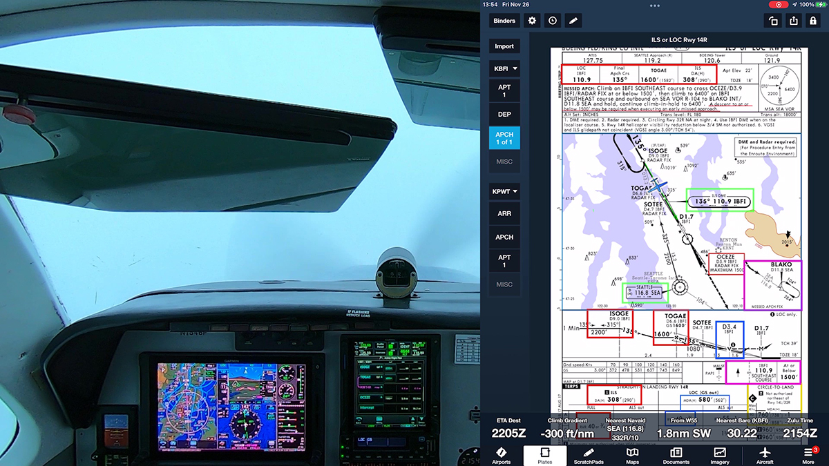
Here are examples of CNFs as shown on the plan view of the ILS Y RWY 27 at KYKM:

CNFs.

5−4−1. j. Waypoints

1. GPS receivers navigate from one defined point to another retrieved from the aircraft’s on board navigational database. These points are waypoints (5-letter pronounceable name), existing VHF intersections, DME fixes with 5-letter pronounceable names and 3-letter NAVAID IDs. Each waypoint is a geographical location defined by a latitude/longitude geographic coordinate. These 5-letter waypoints, VHF intersections, 5-letter pronounceable DME fixes, and 3-letter NAVAID IDs are published on various FAA aeronautical navigation products (IFR Enroute Charts, VFR Charts, Terminal Procedures Publications, etc.)…

3. GPS approaches use fly−over and fly−by waypoints to join route segments on an approach. Fly−by waypoints connect the two segments by allowing the aircraft to turn prior to the current waypoint in order to roll out on course to the next waypoint. This is known as turn anticipation and is compensated for in the airspace and terrain clearances. The MAWP and the missed approach
holding waypoint (MAHWP) are normally the only two waypoints on the approach that are not fly−by waypoints. Fly−over waypoints are used when the aircraft must overfly the waypoint prior to starting a turn to the new course. The symbol for a fly-over waypoint is a circled waypoint. Some waypoints may have dual use; for example, as a fly-by waypoint when used as an IF for a NoPT route and as a fly-over waypoint when the same waypoint is also used as an IAF/IF hold-in-lieu of PT. When this occurs, the less restrictive (fly-by) symbology will be charted. Overlay approach charts and some early stand-alone GPS approach charts may not reflect this convention.

4. Unnamed waypoints for each airport will be uniquely identified in the database. Although the identifier may be used at different airports (for example, RW36 will be the identifier at each airport with a runway 36), the actual point, at each airport, is defined by a specific latitude/longitude coordinate.

5. The runway threshold waypoint, normally the MAWP, may have a five−letter identifier (for example, SNEEZ) or be coded as RW## (for example, RW36, RW36L). MAWPs located at the runway threshold are being changed to the RW## identifier, while MAWPs not located at the threshold will have a five− letter identifier. This may cause the approach chart to differ from the aircraft database until all changes are complete. The runway threshold waypoint is also used as the center of the Minimum Safe Altitude (MSA) on most GPS approaches.

5−4−1. l. Impact of Magnetic Variation on RNAV Systems

1. Differences may exist between charted magnetic courses on ground-based navigational aid
(NAVAID) instrument flight procedures (IFP), area navigation (RNAV) procedures, and RNAV systems on enroute charts, approach charts, and Standard Instrument Departure/Standard Terminal Arrival (SID/STAR) charts. These differences are due to the magnetic variance used to calculate the magnetic course. Every leg of an instrument procedure is first computed along a desired ground track with reference to true north. A magnetic variation correction is then applied to the true course in order to calculate a magnetic course for publication. The type of procedure will determine what magnetic variation value is added to the true course. A ground-based NAVAID IFP applies the facility magnetic variation of record to the true course to get the charted magnetic course. Magnetic courses on RNAV procedures are calculated two different ways. SID/STAR procedures use the airport magnetic variation of record, while IFR enroute charts use magnetic reference bearing. RNAV systems make a correction to true north by adding a magnetic variation calculated with an algorithm based on aircraft position, or by adding the magnetic variation coded in their navigational database. This may result in the RNAV system and the procedure designer using a different magnetic variation, which causes the magnetic course displayed by the RNAV system and the magnetic course charted on the IFP plate to be different. It is important to understand, however, that RNAV systems (with the exception of VOR/DME RNAV equipment) navigate by reference to true north and display magnetic course only for pilot reference. As such, a properly functioning RNAV system, containing a current and accurate navigational database, should still fly the correct ground track for any loaded instrument procedure, despite any differences in magnetic course that may be attributed to magnetic variation application. Should significant differences between the approach chart and the RNAV system avionics’ application of the navigation database arise, the published approach chart, supplemented by NOTAMs, holds precedence.

2. The course into a waypoint may not always be 180 degrees different from the course leaving the previous waypoint, due to the RNAV system avionics’ computation of geodesic paths, distance between waypoints and differences in magnetic variation application. Variations in distances may also occur since RNAV system distance−to−waypoint values are along−track distances (ATD) computed to the next waypoint and the DME values published on underlying procedures are slant−range distances measured to the station. This difference increases with aircraft altitude and proximity to the NAVAID.

5−3−4. Airways and Route Systems

(b) Unpublished RNAV routes are direct routes, based on area navigation capability, between waypoints defined in terms of latitude/longitude coordinates, degree−distance fixes, or offsets from established routes/airways at a specified distance and direction. Radar monitoring by ATC is required on all unpublished RNAV routes, except for GNSS−equipped aircraft cleared via filed published waypoints recallable from the aircraft’s navigation database.

5−4−1. Standard Terminal Arrival(STAR), Area Navigation (RNAV) STAR, and Flight Management System Procedures (FMSP) for Arrivals

This change incorporates updated guidance on resumption of published altitude and speed restrictions, guidance on what is expected of aircrews when issued a “climb via” clearance, and clarifies the expectation that pilots will advise the receiving controller of the altitude being vacated and the altitude they are climbing to when changing frequencies.

For all the details, see this section in the update to the AIM.

i. 5−4−5. Instrument Approach Procedure Charts

This change updates guidance to reflect the fact that the initial approach fix (IAF) waypoint is not an IAF, but an intermediate fix (IF). This change also updates guidance on descent below the minimum descent altitude (MDA).

For all the details, see this section in the update to the AIM.

7−1−11. Flight Information Services (FIS)

This change updates information and guidance to modify outdated information, reflect policy and terminology changes, and address changing technologies.

For all the details, see this section in the update to the AIM.

7−1−14. ATC Inflight Weather Avoidance Assistance

This change was added to expand the meaning of the phrase “when able” when used in conjunction with a clearance to deviate around weather. The clearance to deviate is clarified to allow maneuvering within the lateral limits of the deviation clearance.

For all the details, see this section in the update to the AIM.

New Definitions for Icing PIREPs

The February 9, 2012 edition of the AIM includes an update to section 7-1-21: PIREPS Relating to Airframe Icing. According to the FAA:

This change addresses the change to the icing intensity definitions, quantifiable icing rates, and an updated replacement for current terminology. It would also help satisfy NTSB Safety recommendations A­96­51 and ­060.

The updated definitions are:

1. Light. The rate of ice accumulation requires occasional cycling of manual deicing systems** to minimize ice accumulations on the airframe. A representative accumulation rate for reference purposes is 1/4 inch to one inch (0.6 to 2.5 cm) per hour (See TBL 7-1-7)  on the unprotected part of the outer wing. The pilot should consider exiting the condition.

2. Moderate. The rate of ice accumulation requires frequent cycling of manual deicing systems** to minimize ice accumulations on the airframe. A representative accumulation rate for reference purposes is 1 to 3 inches (2.5 to 7.5 cm) per hour (See TBL 7-1-7)  on the unprotected part of the outer wing. The pilot should consider exiting the condition as soon as possible.

3. Heavy.  The rate of ice accumulation requires maximum use of the ice protection systems to minimize ice accumulations on the airframe. A representative accumulation rate for reference purposes is more than 3 inches (7.5 cm) per hour (See TBL 7-1-7)  on the unprotected part of the outer wing. Immediate exit from the conditions should be considered.

4.  Severe. The rate of ice accumulation is such that ice protection systems fail to remove the accumulation of ice and ice accumulates in locations not normally prone to icing, such as areas aft of protected surfaces and any other areas identified by the manufacturer. Immediate exit from the condition is necessary.

Changes in February 9 2012 Edition of the AIM

The FAA has released the basic version of the February 9 2012 edition of the Aeronautical Information Manual. (You can download the PDF version of the new edition here; the web version presumably will appear on the official publication date.)

According to the Explanation of Changes in the new edition, the key revisions include:

c. 4−1−20. Transponder Operation

This change explains that transponders should be turned on prior to moving on the airport surface – as opposed to “as soon as possible.”

d. 4−3−23. Use of Aircraft Lights

This change aligns the AIM guidance on the use of aircraft lights with AC 120-74A.

e. 4−4−3. Clearance Items

This change adds language to inform pilots of what to expect from controllers concerning clearance limits and associated phraseology.

h. 5−5−16. RNAV and RNP Operations

This change provides guidance for the definition of “established” for RNAV and RNP operations. [For a more detailed discussion of this update, see this post here at BruceAir.]

k. 7−1−21. PIREPS Relating to Airframe Icing

This change addresses the change to the icing intensity definitions, quantifiable icing rates, and an updated replacement for current terminology. It would also help satisfy NTSB Safety recommendations A-96-51 and -060.*

*(A-96-51)

Recommendation:
TO THE FEDERAL AVIATION ADMINISTRATION: Revise the existing aircraft icing intensity reporting criteria (as defined in the Aeronautical Info Manual (AIM) and other FAA literature) by including nomenclature that is related to specific types of aircraft, and that is in logical agreement with existing Federal Aviation Regulation (FARs).